
System for synchronizing lighting control signals and lighting patterns of lighting effect devices

A luminous effect and control signal technology, applied to electroluminescent light sources, lighting devices, light sources, etc., can solve the problems of time difference, triggering luminous effects, and clocks that cannot adjust time delay by themselves, so as to achieve the effect of promoting synchronous performance

Active Publication Date: 2021-01-15
LUMIC TECH INC
View PDF7 Cites 0 Cited by
  • Summary
  • Abstract
  • Description
  • Claims
  • Application Information

AI Technical Summary

Problems solved by technology

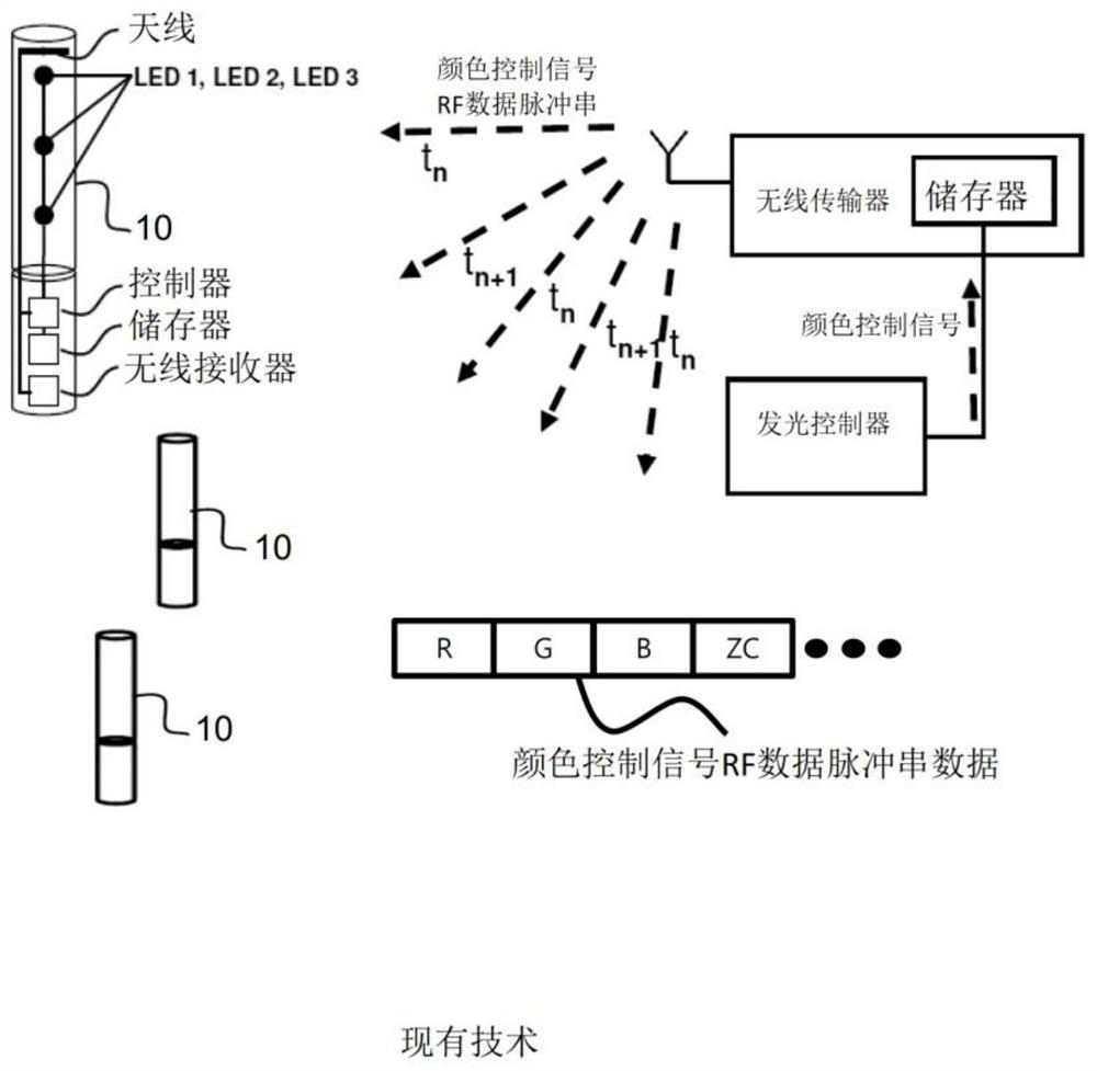
However, the above-mentioned traditional method of synchronizing the remote viewing position with the lighting effect pattern of the live concert venue has the following disadvantages: (1) Once an unexpected time delay occurs at the beginning of the concert venue, each LED light The clock on the wristband cannot adjust the time delay by itself, which will cause the luminous effect to be triggered at the wrong time / interval; due to the expected or predicted time delay at the concert venue, additional time is required before the concert starts It takes a while to calibrate or adjust the clock of each LED light-emitting wristband in advance; (2) although the user can be notified when the concert starts to pull out the battery isolation tab to start the synchronization for the synchronized light-emitting effect Timer, but because the actual running time of each part of the Concert Glow script sometimes changes dynamically, it is almost impossible to follow each part of the Concert Glow script exactly at all actual running times Part of the predetermined schedule is carried out, so once the dynamic changes are imported, the luminous effects produced on all LED luminous wristbands will no longer be carried out in perfect time order; (3) Any time that occurs during the actual playback of the video Delays, e.g. due to broadcast interruptions or video stream buffering delays, can cause significant time differences between the clock on the LED light-up wristband and the original preset clock on the controller at the concert event

Method used


Image

  • System for synchronizing lighting control signals and lighting patterns of lighting effect devices
  • System for synchronizing lighting control signals and lighting patterns of lighting effect devices
  • System for synchronizing lighting control signals and lighting patterns of lighting effect devices

Examples


Embodiment Construction

[0061] In order to achieve the above-mentioned purpose and effect, the technical means and the structure adopted by the present invention are hereby described in detail with respect to the preferred embodiments of the present invention.

[0062] In the following text, several terms or phrases will be used throughout the present invention, which have the following definitions, such as the following definitions:

[0063] The synchronous lighting effect control signal has the following definition: when a series of lighting effect control signals are sequentially generated according to a concert script to wirelessly control the interactive lighting effect device held by the audience at the local location of the live concert A At the same time, audiences who are located in remote locations and also hold the interactive light effect device can also feel the light effect control changes of the interactive light effect device in their hands by watching the streaming video of the live c...


PUM


Abstract

The invention discloses an interactive lighting effect control system for synchronizing lighting effect patterns of remote interactive lighting effect devices. It can be realized to generate synchronous lighting effects remotely while watching lighting effect performances using other interactive lighting effect devices that perform lighting according to the script of the live event venue. The synchronous lighting effect obtained remotely can produce a corresponding virtual simulation perception when watching live streaming video, as if attending the same concert venue. Due to the color control signal generation method and the use of the color control pattern mixing module, the delay of the remote generation of light effect changes relative to the light effect observed in the live video of the concert venue is very low, so that the remote can generate high-efficiency light effect patterns, The color control pattern mixing module is used to generate the mixed video frame including the color control pattern.

Description

technical field [0001] The present invention relates to a system for synchronizing the luminous effect pattern and luminous effect control signal of an interactive luminous effect device; in particular, it relates to a system for enabling remote interactive luminous light while watching the streaming video live broadcast of live performance activities at the first position A method and system for synchronizing luminous effect patterns and luminous effect control signals of an effect device to generate synchronous dynamic interactive luminous effects and realize virtual simulation perception as if attending the same concert venue. Background technique [0002] Interactive lighting effect devices such as LED lighting wristbands are very common portable electronic devices, and are often used to achieve large-scale interactive lighting effects in various event venues, such as concerts, sports events, public gatherings, church activities , political gatherings, educational instit...

Claims


Application Information

Patent Timeline
Patent Type & Authority Patents(China)
IPC IPC(8): H05B45/10H05B45/20H05B47/19H05B44/00
CPCH05B45/10H05B45/20
Inventor 吕英阁黄大维林达人张志铭王文志
Owner LUMIC TECH INC
Learn More