
Secondary fluorescent wide-angle multifunctional imaging device

An imaging device and secondary fluorescence technology, applied in computerized tomography scanners, echo tomography, etc., can solve problems such as inability to perform effective large-scale irradiation, achieve stable rotation, wide range of functions and application sites, and occupancy of plane space little effect

Pending Publication Date: 2019-05-10
深圳市纳诺艾医疗科技有限公司
View PDF0 Cites 4 Cited by
  • Summary
  • Abstract
  • Description
  • Claims
  • Application Information

AI Technical Summary

Problems solved by technology

Although the size of the equipment is slightly smaller than the traditional horizontal type, it is still larger
The tube technology is mostly the traditional Coolidge tube, and the irradiation angle is generally about 10 degrees, so effective large-scale irradiation cannot be performed within a limited distance

Method used


Image

  • Secondary fluorescent wide-angle multifunctional imaging device
  • Secondary fluorescent wide-angle multifunctional imaging device
  • Secondary fluorescent wide-angle multifunctional imaging device

Examples


Embodiment 1

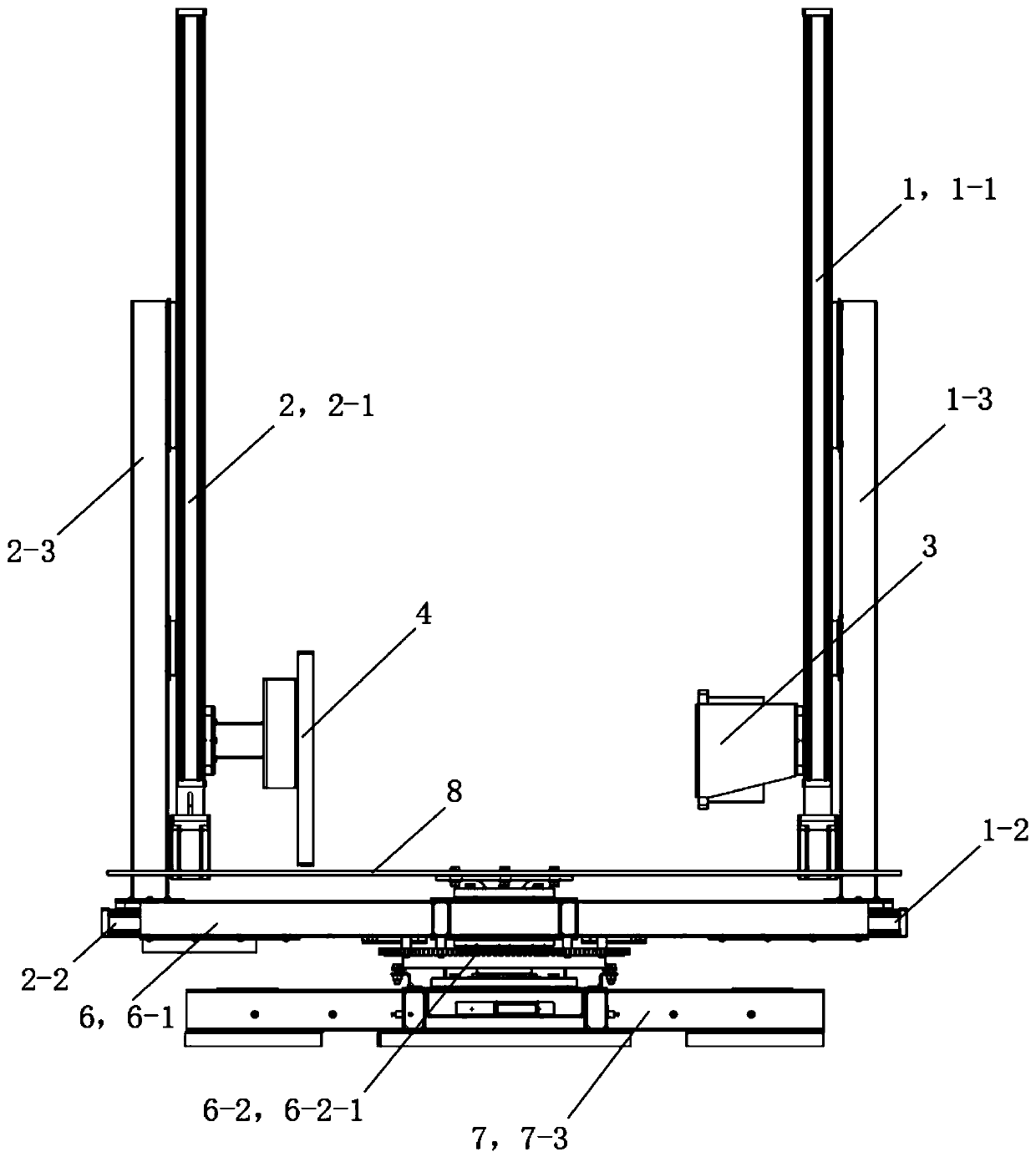
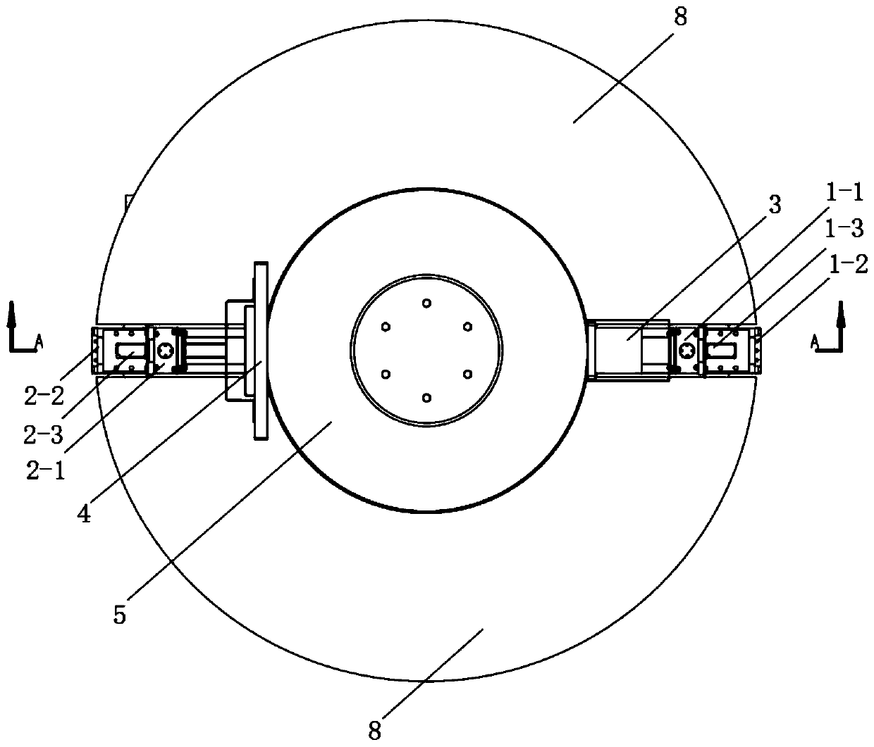
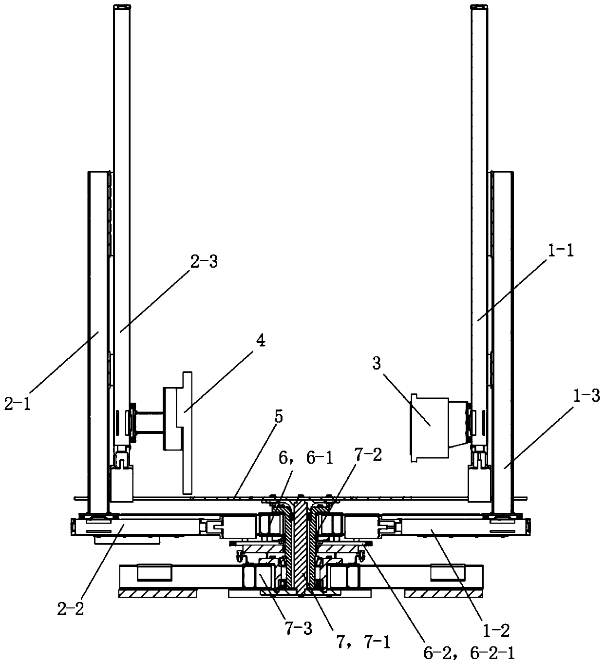
[0047] See Figure 1 to Figure 12 The secondary fluorescence wide-angle multifunctional imaging device of this embodiment includes a light source adjustment mechanism 1, a detection plate adjustment mechanism 2, a wide-angle light source 3, a detection plate 4, a fixed tray 5, a rotation mechanism 6, a support seat 7 and an outer platform 8. The wide-angle light source 3 and the detection board 4 are respectively arranged on both sides of the center of the fixed tray 5 , and the installation positions of the wide-angle light source 3 and the detection board 4 on the horizontal plane projection are symmetrical along the center of the fixed tray 5 . The light source adjustment mechanism 1 is used to adjust the height of the wide-angle light source 3 and the distance between the wide-angle light source 3 and the detection board 4 . The detection board adjustment mechanism 2 is used to adjust the height of the detection board 4 and the distance between the detection board 4 and th...

Embodiment 2

[0072] This embodiment is basically the same as Embodiment 1, the difference is:

[0073] This embodiment also includes a radiation shielding bin. The light source adjustment mechanism 1 , the detection board adjustment mechanism 2 , the wide-angle light source 3 , the detection board 4 , the fixed tray 5 and the rotation mechanism 6 are all located in the radiation shielding chamber 9 . The radiation shielding cabin is provided with a cabin door.


PUM


Abstract

The invention discloses a secondary fluorescent wide-angle multifunctional imaging device which comprises a light source adjusting mechanism, a detection plate adjusting mechanism, a wide-angle lightsource, a detection plate, a fixed tray and a rotating mechanism. The wide-angle light source and the detection plate are disposed at the two sides of the center of the fixed tray respectively; the light source adjusting mechanism is used for adjusting the height of the wide-angle light source and the distance between the wide-angle light source and the detection plate; the detection plate adjusting mechanism is used for adjusting the height of the detection plate and the distance between the detection plate and the wide-angle light source; the rotating mechanism is used for enabling the wide-angle light source and the detection plate to rotate synchronously with the fixed tray as the axis. The secondary fluorescent wide-angle multifunctional imaging device can perform low-dose imaging onvarious parts of the human body by moving horizontally and vertically; meanwhile, through the rotating mechanism, the wide-angle light source and the detection plate can rotate synchronously with thefixed tray as the axis, and vertical rotary scanning and perspective analysis of various parts of the human body are realized; the device adjusts imaging through wide-angle cone light and is small inplane space occupation, diversified in function and applicable to various parts of the human body.

Description

technical field [0001] The invention relates to a secondary fluorescence wide-angle multifunctional imaging device. Background technique [0002] DR equipment and CT functions and equipment are often separated. CT mostly uses fan-shaped section light and the corresponding fan-shaped detection plate, while DR mostly uses cone-shaped narrow-angle light below 10 degrees and flat-panel detection. There is also a large difference in the power used between the two. DR generally requires tens of thousands of watts of power, while CT requires more than 100,000 watts. In addition, the direction of the DR operation detection board can be vertical or horizontal and mostly static, while CT patients generally need to lie down horizontally, and the CT ring frame needs to rotate around the patient at high speed. The two cannot be combined, either functionally or cost-effectively. At the same time, the land occupation and cost of the two types of equipment are expensive, and the consumpt...

Claims


Application Information

Patent Timeline
IPC IPC(8): A61B6/03
Inventor 程钊
Owner 深圳市纳诺艾医疗科技有限公司
Learn More