
An in-situ compensation method for residual magnetic field for single-beam serf atomic magnetometers

A technology of residual magnetic field and atomic magnetic intensity, which is applied in the use of magneto-optical equipment for magnetic field measurement, magnetic field size/direction and other directions, which can solve the problems of poor anti-interference ability and low compensation accuracy.

Inactive Publication Date: 2020-09-25
BEIHANG UNIV
View PDF9 Cites 0 Cited by
  • Summary
  • Abstract
  • Description
  • Claims
  • Application Information

AI Technical Summary

Problems solved by technology

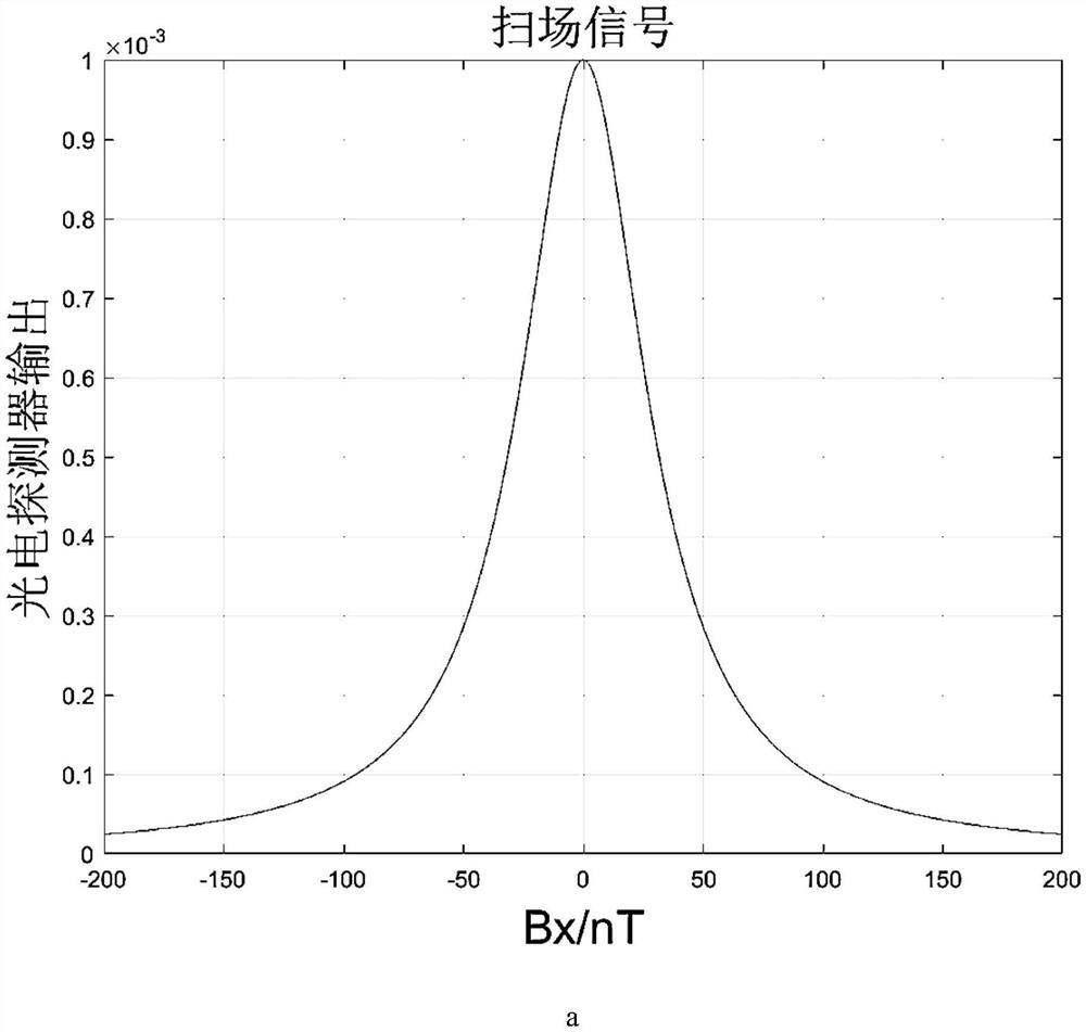
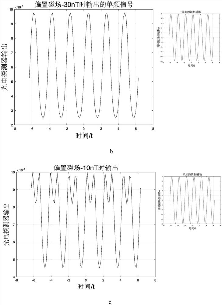
[0004] The technical problem to be solved by the present invention is: to overcome the problems such as poor anti-interference ability and low compensation accuracy that exist in the residual magnetic field compensation of the existing conventional SERF atomic magnetometer for single beam, in the single beam SERF magnetometer Add a large offset in the non-sensitive axis direction to increase the zero field resonance width to make the output response more obvious, and then perform three-axis modulation to observe the FFT of the output signal for compensation, so that the residual magnetic field can be more accurately compensated to the zero point

Method used


Image

  • An in-situ compensation method for residual magnetic field for single-beam serf atomic magnetometers
  • An in-situ compensation method for residual magnetic field for single-beam serf atomic magnetometers
  • An in-situ compensation method for residual magnetic field for single-beam serf atomic magnetometers

Examples


Embodiment Construction

[0022] The present invention will be further described below in conjunction with the accompanying drawings and specific embodiments.

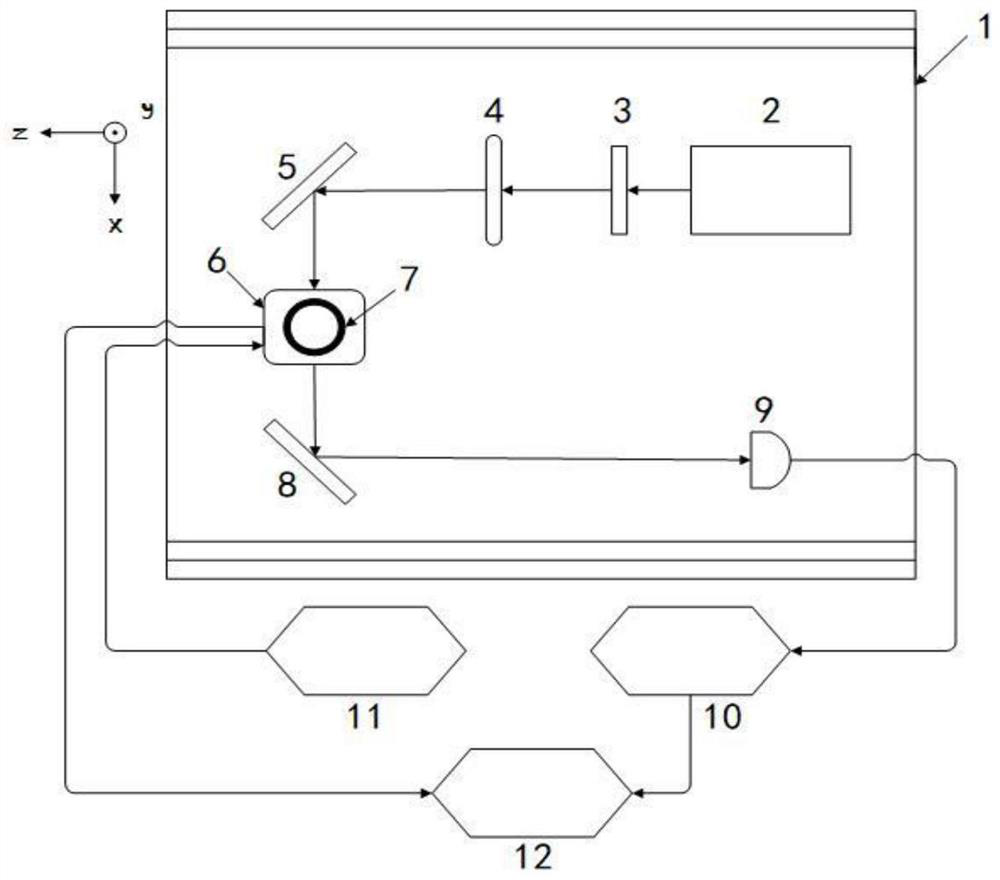
[0023] like figure 1 As shown, the device for the experimental verification of the method of the present invention includes: a magnetic shield barrel 1, a laser 2, a polarizer 3, a 1 / 4 wave plate 4, a first plane mirror 5, a three-axis magnetic compensation coil 6, and an alkali metal gas chamber 7. A second flat mirror 8 , a photodetector 9 , a preamplifier 10 , a function generator 11 , and a display interface 12 . The magnetic shielding barrel 1 is a three-layer permalloy magnetic shielding barrel. First, the laser generates a laser beam that satisfies the laser wavelength at the center of the D1 line of the alkali metal atom, and is used for pumping and detection at the same time. The polarizer generates linearly polarized light, and then the 1 / 4 wave plate converts the linearly polarized light into circularly polarized light. , and then ...


PUM


Abstract

The invention relates to a method for in-situ compensation of a residual magnetic field of a single-beam SERF (Spin-Exchange-Relaxation-Free) atom magnetometer, and belongs to the field of atom magnetometers. Due to the fact that the SERF atom magnetometer is extremely high in precision, an SERF state meeting the working state requirements is more dependent on a high-quality zero-magnetic environment, passive compensation is difficult to achieve, and an active compensation method of locking an extreme point of the output curve is greatly affected by the environment, the noise and the like; anddue to the fact that the single-beam atom magnetometer only has a beam of light, the magnetic field compensation methods for a double-beam atom magnetometer are limited. According to the designed method, an offset is added in a direction of a non-sensitive axis of the single-beam SERF magnetometer in order to increase the resonance width of a zero field, so that the output response is more obvious, and FFT of an output signal is compensated by three-axis modulation, so that the residual magnetic field can be more accurately compensated to the zero point, and the method can be applied to the fields of automation, miniaturization and the like of cardio-cerebral magnetic measurement of the ultra-high-precision SERF atom magnetometer in the future.

Description

technical field [0001] The invention relates to an in-situ residual magnetic field compensation method for a single-beam SERF (Spin-Exchange-Relaxation-Free, no spin exchange relaxation) atomic magnetometer, belonging to the field of atomic magnetometers. Background technique [0002] Atomic magnetometer is one of the effective means of magnetic field measurement. With the continuous development of magnetometer and the continuous improvement of research level, it plays an important role in the fields of basic scientific research, geological exploration, aerial magnetic measurement and heart-brain magnetic measurement. Indispensable role, which puts forward a higher level of requirements for the accuracy of the magnetometer, SERF atomic magnetometer is the representative of ultra-high precision magnetometer in recent years, how to achieve high-quality SERF state is to achieve The basis for ultra-high precision measurements. [0003] The passive compensation method can only s...

Claims


Application Information

Patent Timeline
Patent Type & Authority Patents(China)
IPC IPC(8): G01R33/032
Inventor 丁铭蔡佳书尹彦王婧尹凯峰周斌权韩邦成
Owner BEIHANG UNIV
Learn More