
Mobile positioning

a mobile positioning and positioning technology, applied in the field of mobile positioning, can solve the problems of numerous hz, 1575 mhz frequency errors, and substantial errors at the demodulator, and achieve the effects of sufficient stability in satellite signal demodulation, quick and accurate frequency compensation, and effective compensation

Active Publication Date: 2010-04-06
WSOU INVESTMENTS LLC
View PDF21 Cites 5 Cited by
  • Summary
  • Abstract
  • Description
  • Claims
  • Application Information

AI Technical Summary

Benefits of technology

[0015]Advantageously, producing a second frequency signal independent of the first frequency signal and the detector being used to compensate for errors caused by the second frequency signals by using interpolation allows more reliable and sensitive decoding than that disclosed in U.S. Pat. No. 5,841,396. The inventor realised that when the demodulation signals are locked to the frequency of base station signals as in U.S. Pat. No. 5,841,396, they can only be determined to an accuracy of approximately ±0.5 ppm. When a weak GPS signal is being acquired or tracked a GPS engine may require stability in the order of ±0.01 ppm or better. Further, a simple and inexpensive non-temperature compensated crystal may be used as the second frequency source. The second frequency signal will then freely drift so that the demodulation of satellite signals will correspondingly fluctuate, but this fluctuation can be accurately corrected by the decoder. The interpolation enables the difference between the first and second signals to be detected by a resolution finer than a single period of either of the first and second signals that are being compared. This is particularly useful as typically the first and second frequency signals have significantly lower frequencies than the satellite signals and hence mere comparison of the first and second signals with a single clock cycle resolution would result in substantial errors at the demodulator. Hence, the comparison with a single second frequency signal clock cycle, for example, on 10 MHz frequency may cause an error of numerous Hz on a 1575 MHz frequency.
[0043]It should be appreciated that the embodiments of any one aspect may produce corresponding advantages when combined with different other aspects as well and that they can be combined where applicable.

Problems solved by technology

This is particularly useful as typically the first and second frequency signals have significantly lower frequencies than the satellite signals and hence mere comparison of the first and second signals with a single clock cycle resolution would result in substantial errors at the demodulator.
Hence, the comparison with a single second frequency signal clock cycle, for example, on 10 MHz frequency may cause an error of numerous Hz on a 1575 MHz frequency.
The inventor further realised that the arrangement of U.S. Pat. No. 5,841,396 is prone to errors in GPS reliability if the first frequency signal is updated at a relatively low rate such as 0.5 to 1 Hz.

Method used


Image

  • Mobile positioning
  • Mobile positioning
  • Mobile positioning

Examples


Embodiment Construction

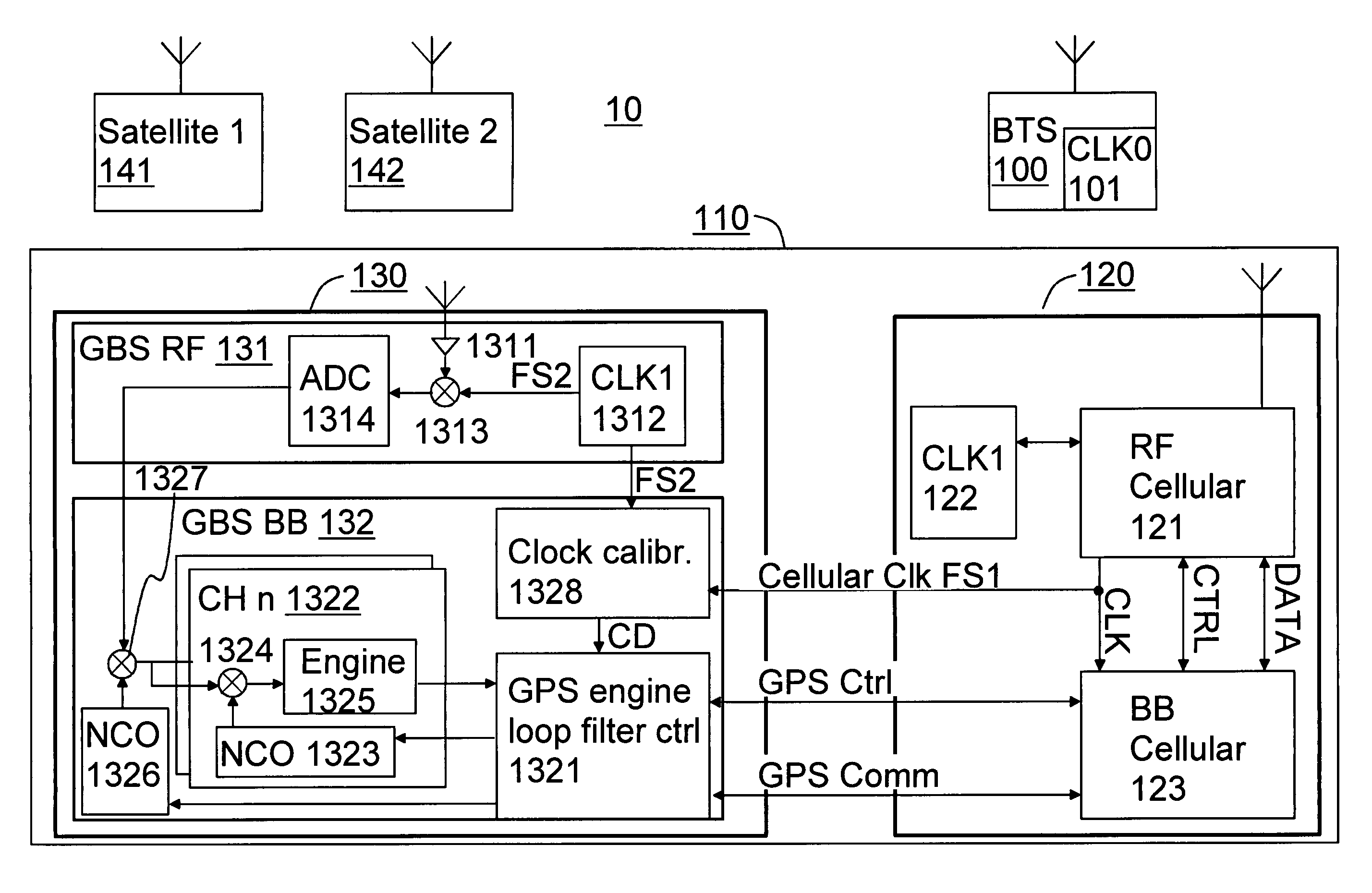
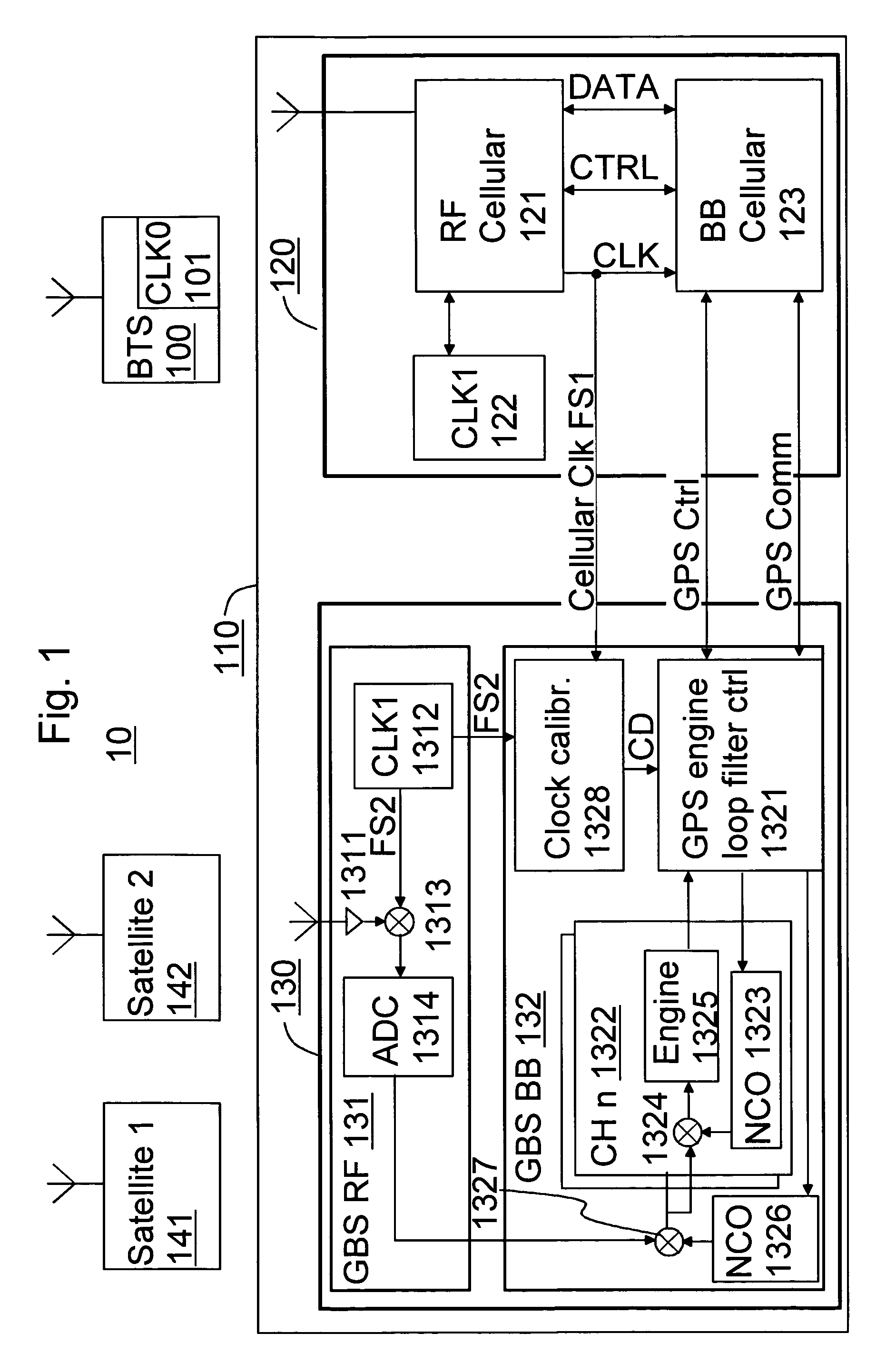
[0051]FIG. 1 is a simplified schematic drawing of a system 10 according to the preferred invention. FIG. 1 illustrates the components of the system useful to describe the invention, that is a base station 100, a mobile device 110 comprising a cellular communications block 120 and satellite positioning block 130, and two satellite transmitters 141 and 142.

[0052]The base station 100 comprises a base station frequency source that should control the base station so that the frequency of its radio signals is accurate to ±0.05 ppm.

[0053]The communications block 120 comprises the typical means for communicating with a cellular base station, including a cellular Radio Frequency (RF) block 121, a cellular clock 122 for producing a first frequency signal for controlling the frequencies of the RF block 122 and a cellular Base Band (BB) block 123. The communications block 120 has been connected with the satellite positioning block 130 and can communicate over a radio communication channel with ...


PUM


Abstract

A dual mode device (110) comprising a communications block (120) and a satellite positioning block (130), each comprising respective Base Band (BB) blocks (123, 132) and crystals or frequency sources (122, 1312). The communications crystal (122) provides a cellular clock signal (FS1) to the satellite positioning block (130), which monitors the difference in the frequencies the crystals produce (FS1, FS2), using Vernier interpolation to gain a resolution greater than one clock cycle. The positioning crystal (1312) is used independent of the cellular crystal to demodulate satellite signals. The positioning BB (132) tracks the demodulated satellite signals compensating any errors caused by the positioning crystal signals (FS2) to the demodulation, using the information resulting from the monitoring. The communications crystal is capable to network based calibration and the positioning BB can compensate for the fluctuation thus caused in the cellular clock signal (FS1).

Description

PRIORITY STATEMENT[0001]This application claims priority to UK Patent Application Number 0307030.7, filed on Mar. 27, 2003.FIELD OF THE INVENTION[0002]This invention relates to mobile positioning. The invention relates particularly, but not exclusively, to increasing the reliability and capability of satellite based mobile positioning with the assistance of a radio telecommunications network.BACKGROUND OF THE INVENTION[0003]Satellite positioning such as the Global Positioning System (GPS) is based on providing a receiver with frequent radio sequences containing Code Division Multiple Access (CDMA) coded data by decoding which the receiver can determine very accurately the radio propagation delay relative to the satellite. With the signals of at least four different satellites, a GPS receiver can determine its position.[0004]When switched on, a GPS receiver will first search for satellites in a so-called acquisition process. In successful acquisition a GPS receiver determines very ac...

Claims


Application Information

Patent Timeline
Patent Type & Authority Patents(United States)
IPC IPC(8): H04B7/185H04W24/00G01S1/00G01S3/52G01S19/23H04B7/14
CPCG01S19/235
Inventor EADE, PHILIP GEOFFREY
Owner WSOU INVESTMENTS LLC
Learn More