
Tyre unloader

A kind of unloader, tire technology, applied in the direction of hand-held tools, manufacturing tools, etc., can solve the problem of unable to meet the needs of rapid development of rail transit, lack of professional machinery, etc., to improve the automatic production line of rail transit, fill technology and market blank effect

Pending Publication Date: 2019-05-14
HUBEI HEQIANG MACHINERY DEV LIMITED BY SHARE
View PDF0 Cites 0 Cited by
  • Summary
  • Abstract
  • Description
  • Claims
  • Application Information

AI Technical Summary

Problems solved by technology

[0002] As far as we know, for a wheel composed of a wheel core and a wheel rim, there is no professional machine so far to remove the wheel rim from the wheel core, and of course it cannot meet the needs of the rapid development of modern rail transit.

Method used


Image

  • Tyre unloader
  • Tyre unloader

Examples


Embodiment Construction

[0009] The present invention will be further described below in conjunction with the accompanying drawings.

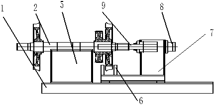
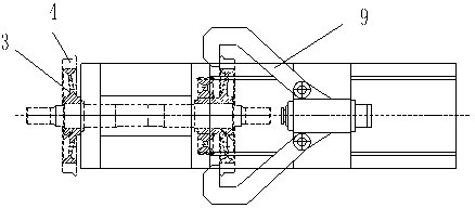
[0010] Such as Figure 1 to Figure 2 As shown, the present invention discloses a tire unloading machine, which has a base 1, an oil cylinder seat 7 is arranged on one end of the base 1, and an axial oil cylinder 8 is arranged on a fixed support. The oil cylinder is a compound oil cylinder, and movable pull hooks 9 are symmetrically arranged on both sides of the piston rod sleeve of the compound oil cylinder, and the hook heads are opposite to each other. The other end of the base is provided with a support shaft seat 5, and a support is provided on the base, corresponding to the wheels. Wheel bracket.

[0011] The composite oil cylinder has three layers, which are respectively a piston rod, a piston rod sleeve and a cylinder sleeve from the inside to the outside.

[0012] Working process of the present invention is as follows:

[0013] When unloading the tire, first...


PUM


Abstract

The invention discloses a tyre unloader. The tyre unloader comprises a base, a fixing supporting seat is arranged at one end of the base, an axial oil cylinder is arranged on the fixing supporting seat, and the oil cylinder is a composite oil cylinder; movable drag hooks are symmetrically arranged on the two sides of a piston rod sleeve of the composite oil cylinder, and the drag hook heads are opposite to each other; and a shaft supporting seat is arranged at the other end of the base, and a wheel supporting bracket is arranged on the base and located under wheels. The tyre unloader has the beneficial effects that a tyre can be mechanically and automatically retracted from a wheel core, the time and the labor are saved, the technical and market gaps are filled, and the automatic production line of rail transit is further improved.

Description

technical field [0001] The invention relates to an equipment machine for rail transit, in particular to a tire unloading machine, which is suitable for unloading split wheels. Background technique [0002] As far as we know, for a wheel composed of a wheel core and a wheel rim, there is no professional machine so far to remove the wheel rim from the wheel core. Of course, it cannot meet the needs of the rapid development of modern rail transit. Contents of the invention [0003] In order to solve the problem of deficiencies in the prior art, the present invention provides a hoop unloading machine, which has a simple structure and strong practicability, can quickly unload the hoop, and saves time and effort. [0004] In order to achieve the above object, the technical solution of the present invention is a wheel unloading machine, which has a base, a fixed support is provided at one end of the base, and an axial oil cylinder is arranged on the fixed support. The oil cylind...

Claims


Application Information

Patent Timeline
IPC IPC(8): B25B27/02
Inventor 喻国锋童俊军张霄喻侃
Owner HUBEI HEQIANG MACHINERY DEV LIMITED BY SHARE
Features
  • Generate Ideas
  • Intellectual Property
  • Life Sciences
  • Materials
  • Tech Scout
  • Unparalleled Data Quality
  • Higher Quality Content
  • 60% Fewer Hallucinations
Learn More