Fish controller with touch control locking mechanism

A touch and trigger technology, applied in fishing, fishing accessories, applications, etc., can solve the problems of operation fatigue, the fish controller is not suitable for long-distance fish retrieval, and inconvenient to use, and achieves the effect of reducing operation fatigue.

Inactive Publication Date: 2019-05-21
YANGZHOU YUANSHENG MACHINERY
View PDF0 Cites 4 Cited by
  • Summary
  • Abstract
  • Description
  • Claims
  • Application Information

AI Technical Summary

Problems solved by technology

[0002] As a kind of fishing equipment, the fish control device has been more and more accepted and used by the majority of fishing enthusiasts. When the commonly used fish control device is used, it needs to be manually controlled to keep it open, which is inconvenient to use and can be locked for a long time. Operational fatigue caused by pulling the trigger, and commonly used fish control devices are not suitable for long-distance fishing

Method used


Image

  • Fish controller with touch control locking mechanism
  • Fish controller with touch control locking mechanism
  • Fish controller with touch control locking mechanism

Examples


no. 1 example

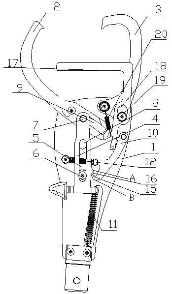
[0026] Such as figure 1 As shown, the fish control device with a touch control locking mechanism includes a base 1, the base 1 is a double-layer splint arranged at intervals and connected to each other, and the front end of the base 1 is provided with a left jaw 2 and a The right jaw 3, wherein the left jaw 2 is a movable chuck, the right jaw 3 is a fixed chuck, the base 1 is also connected with a trigger 4 for driving the left jaw 2 to open, the tail end of the trigger 4 is connected to the base A first elastic member 11 is connected between the tail ends of 1, and the first elastic member 11 is a tension spring.

[0027] The middle part of the trigger 4 is provided with a first chute 5 extending forward, the base 1 is provided with a first guide pin 6 cooperating with the first chute 5, the front end of the trigger 4 is connected with a second pin 7, the base 1 is provided with a second chute 8 extending forward, and the left jaw 2 is provided with an arc-shaped groove 9, a...

no. 2 example

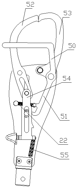
[0034] As shown in the figure, the structure of the second embodiment is basically the same as that of the first embodiment, the difference is that the trigger piece 50 is L-shaped, and the vertical section is integrated with the front end of the locking piece 51, the trigger piece 50 The horizontal section is horizontally arranged on one side of the left jaw 52 and the right jaw 53, so that when the left jaw 52 or the right jaw 53 extends into the fish mouth, the horizontal section of the trigger 50 can be pushed to rotate, thereby driving the locking piece 51 counterclockwise Turning makes the trigger 54 reset under the action of the first elastic member 55, thereby driving the left jaw 2 and the right jaw 3 to close.

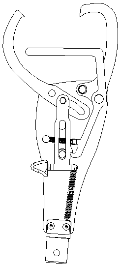
[0035] image 3 It is a structural diagram of the left jaw 52 and the right jaw 53 in the open state of the second embodiment, and the specific principle is the same as that of the first embodiment, which will not be repeated here.

no. 3 example

[0037] Such as Figure 4 As shown, the structure of the third embodiment is basically the same as that of the second embodiment, the difference is that the first elastic member 20 is a compression spring, one end of the compression spring 20 is connected to the first guide pin 21, and the other end is connected to the The rear end of the first sliding groove 23 of the trigger 22.

[0038] The second elastic member 26 adopts a compression spring, and the locking member 24 is provided with a guide rod 25 and a guide seat 27 cooperating with the guide rod 25. The guide rod 25 slides and is inserted in the guide seat 27, and the second elastic member 26 is inserted in the guide rod. 25 on.

[0039] The working principle of this embodiment is similar to that of the first embodiment, and will not be repeated here;


PUM


Abstract

The invention discloses a fish controller with a touch control locking mechanism, and relates to the field of fishing gear articles. The fish controller with the touch control locking mechanism comprises a base, wherein the front end of the base is provided with a left clamping jaw and a right clamping jaw, wherein the left clamping jaw and the right clamping jaw are matched with each other; a locking piece for locking the trigger position when the left and right jaws are kept open is also movably connected in the base; the base is also connected with a trigger piece which is used for automatically triggering the locking piece to act after the left clamping jaw or the right clamping jaw extends into a fish mouth so as to drive the left clamping jaw and the right clamping jaw to close. Whenthe fish controller is in use, the trigger is pulled or pushed, so that the left clamping jaw and the right clamping jaw are opened, meanwhile, the position of a wrench is locked by the locking piece, so that the left clamping jaw and the right clamping jaw are kept in an opened state, thereby greatly reducing the operation fatigue caused by long-time pulling of the trigger by an operator. According to the design of the trigger, the matched left clamping jaw and the matched right clamping jaw can be automatically locked, so that the fish controller can be used conveniently and can take fish for a long distance.

Description

technical field [0001] The invention relates to the field of fishing gear supplies, in particular to a fish control device with a touch control locking mechanism. Background technique [0002] As a kind of fishing equipment, the fish control device has been more and more accepted and used by fishing enthusiasts. When the commonly used fish control device is used, it needs to be manually controlled to keep it open, which is inconvenient to use and can be buckled for a long time. In addition, the commonly used fish control device is not suitable for long-distance fishing. Contents of the invention [0003] The invention provides a fish control device with a touch control locking mechanism, which makes it possible to take fish from a long distance, and greatly reduces the operator's fatigue caused by pulling the trigger for a long time. [0004] The technical solution to achieve the above purpose is: a fish control device with a touch control locking mechanism, including a b...

Claims


Application Information

Patent Timeline
Patent Type & Authority Applications(China)
IPC IPC(8): A01K97/14
Inventor 徐志林
Owner YANGZHOU YUANSHENG MACHINERY
Why Eureka
Try Eureka