
Channel state information CSI coding method and device, storage medium and processor

A channel state information and processor technology, applied in the field of communication, can solve the problem that the location of various CSI information cannot be reasonably arranged, and achieve the effect of improving BLER performance

Active Publication Date: 2019-05-24
ZTE CORP
View PDF4 Cites 0 Cited by
  • Summary
  • Abstract
  • Description
  • Claims
  • Application Information

AI Technical Summary

Problems solved by technology

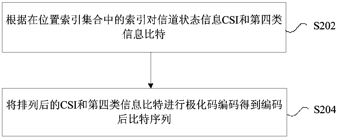
[0005] Embodiments of the present invention provide a method and device, a storage medium, and a processor for channel state information CSI coding, so as to at least solve the problem in the related art that the positions of various types of information in the CSI report cannot be reasonably arranged

Method used


Image

  • Channel state information CSI coding method and device, storage medium and processor
  • Channel state information CSI coding method and device, storage medium and processor
  • Channel state information CSI coding method and device, storage medium and processor

Examples


Embodiment 1

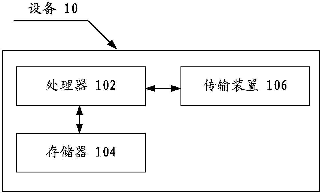
[0019] The method embodiment provided in Embodiment 1 of the present application may be executed in a device, a computer terminal, or a similar computing device. Take running on the device as an example, figure 1 It is a block diagram of the hardware structure of the equipment of the method for encoding channel state information CSI according to the embodiment of the present invention. Such as figure 1 As shown, the device 10 may include one or more (only one is shown in the figure) processors 102 (the processors 102 may include but not limited to processing devices such as microprocessors MCUs or programmable logic devices FPGAs), for storage Data storage 104, and transmission means 106 for communication functions. Those of ordinary skill in the art can understand that, figure 1 The shown structure is only for illustration, and it does not limit the structure of the above-mentioned electronic device. For example, device 10 may also include figure 1 more or fewer componen...

Embodiment approach 1

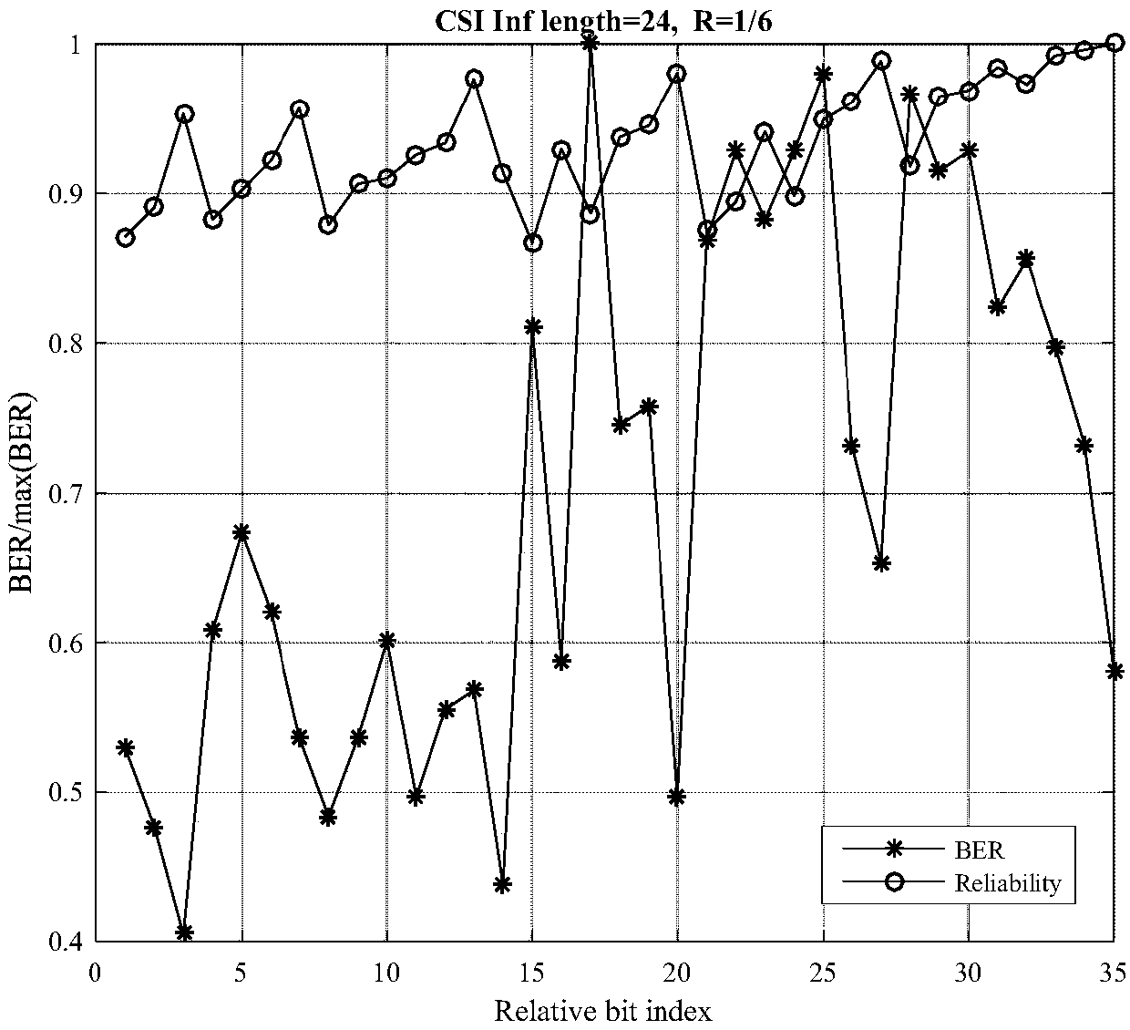
[0074] Such as image 3 As shown, the BER corresponding to the location with a small index number is also small. Therefore, in this embodiment, the method of placing CSI in the location index set is:

[0075] (1) Place the first type of information bits at the (L_CRI+L_RI) indexes with the smallest serial number in the position index;

[0076] (2) place the fourth type of information bit at the L_A index with the largest index in the position index;

[0077] (3.1) Place the second type of information bits and the third type of information bits in the remaining positions according to the index size (from small to large or from large to small) in turn;

[0078] At this time, the sequence of various types of information in the CSI report is as follows:

[0079] Type I information bits

Type II information bits

Type III information bits

Type 4 Information Bits

[0080] or,

[0081] Type I information bits

Type III information bits

Type...

Embodiment approach 2

[0089] Such as image 3 As shown, the position with a small index number corresponds to a small BER. Therefore, in this embodiment, the way to place CSI in the index set is:

[0090] (1) Place the first type of information bits at the (L_CRI+L_RI) indexes with the smallest serial number in the position index;

[0091] (2) placing the second type of information bits at the L_Pad indices with the lowest reliability in the position index;

[0092] (3.1) Place the third type of information bits and the fourth type of information bits in the remaining positions according to the index size (from small to large or from large to small) in turn; or,

[0093] (3.2) Place the third type of information bits and the fourth type of information bits in the remaining positions in sequence according to the index reliability (from small to large or from large to small).


PUM


Abstract

The invention provides a channel state information (CSI) coding method and device. Storage medium and processor, The method comprises the following steps of: placing the first type of information bitsof the CSI on the first type of position indexes of the position index set according to the indexes in the position index set, determining an index of a second type of information bits of the CSI, athird type of information bits of the CSI and a fourth type of information bits in the index set from indexes except the first type of position indexes determined by the first type of information bitsin the position index set; Or placing the fourth type of information bits on the fourth type of position indexes of the index set, and determining the indexes of the first type of information bits, the second type of information bits and the third type of information bits of the CSI in the index set from the indexes except the fourth type of position indexes determined by the fourth type of information bits in the position index set. Through the method and the device, the problem that the positions of various types of information in CSI reporting cannot be reasonably arranged in the prior artis solved.

Description

technical field [0001] The present invention relates to the field of communications, in particular to a method and device for encoding CSI of channel state information, a storage medium and a processor. Background technique [0002] The control channel in 5G NR (New Radio) adopts the Polar code coding method. The coding process of the Polar code is x=u*G, where u includes information bits and parity bits, and x is The coded bit sequence, G is a generator matrix (Generator Matrix) of the Polar code, and the dimension of the generator matrix G is N*N, where N is a power of 2. For polar codes, the reliability (reliability) and BER (BitError Ratio, bit error rate) of different input bit indexes (bit index, 0~N-1) are different. In order to improve the performance of polar codes, it is usually necessary to The polar code input bit sequence is mapped to an index position with high reliability or low BER. [0003] In 5G NR (New Radio, New Radio), a joint coding (Joint coding) mec...

Claims


Application Information

Patent Timeline
IPC IPC(8): H04B7/0456H04B7/06H04L1/00
CPCH04L1/0056H04B7/0626H03M13/136H03M13/23H04B7/0632H04B7/0639H04L1/0026H03M13/1102H04B7/063H04B7/0636H03M13/13H03M13/2957H04W28/18H04L5/0057H04L1/0072H04L1/0057
Inventor 陈梦竹许进徐俊吴昊
Owner ZTE CORP
Learn More