
Physical sound amplifying device

A kind of loudspeaker device and physical technology, which is applied in the direction of sub-bureau voice amplifiers, sound-generating equipment, advanced technology, etc., can solve the problems of mobile phone power consumption, small effect, and difficulty in carrying loudspeaker equipment, and achieve the effect of improving the playback volume and playback effect

Pending Publication Date: 2019-05-24
GUANGZHOU ZHEXI CREATIVE DESIGN CO LTD
View PDF0 Cites 1 Cited by
  • Summary
  • Abstract
  • Description
  • Claims
  • Application Information

AI Technical Summary

Problems solved by technology

[0002] With the development of science and technology, the functions of mobile phones are becoming more and more powerful, bringing more fun to people's lives. Mobile phones basically have music and video playback functions, so many people are used to turning on their mobile phones to enjoy a piece of music or music in their spare time. Video, however, on the one hand, because there is no special mobile phone holder, it can only be held in a handheld state when playing audio, which is relatively easy to fatigue and cannot free up hands to handle other things, which is not very convenient. On the other hand, it is generally through the mobile phone speaker The sounds that are emitted are relatively small and the effect is not good. The problem of mobile phone sound can be solved by wearing earphones or external speakers and other amplifying equipment, but wearing earphones will cause a lot of inconvenience. In the prior art, most of the amplifying devices or equipment All need to provide power through the power supply to realize the sound amplification function, and because most power supplies cannot be carried with you, it is difficult to carry the sound amplification equipment, or it needs to consume the power of the mobile phone, which reduces the use time of the mobile phone

Method used


Image

  • Physical sound amplifying device
  • Physical sound amplifying device
  • Physical sound amplifying device

Examples


Embodiment Construction

[0032] The following will clearly and completely describe the technical solutions in the embodiments of the present invention with reference to the accompanying drawings in the embodiments of the present invention. Obviously, the described embodiments are only some, not all, embodiments of the present invention. Based on the embodiments of the present invention, all other embodiments obtained by persons of ordinary skill in the art without making creative efforts belong to the protection scope of the present invention.

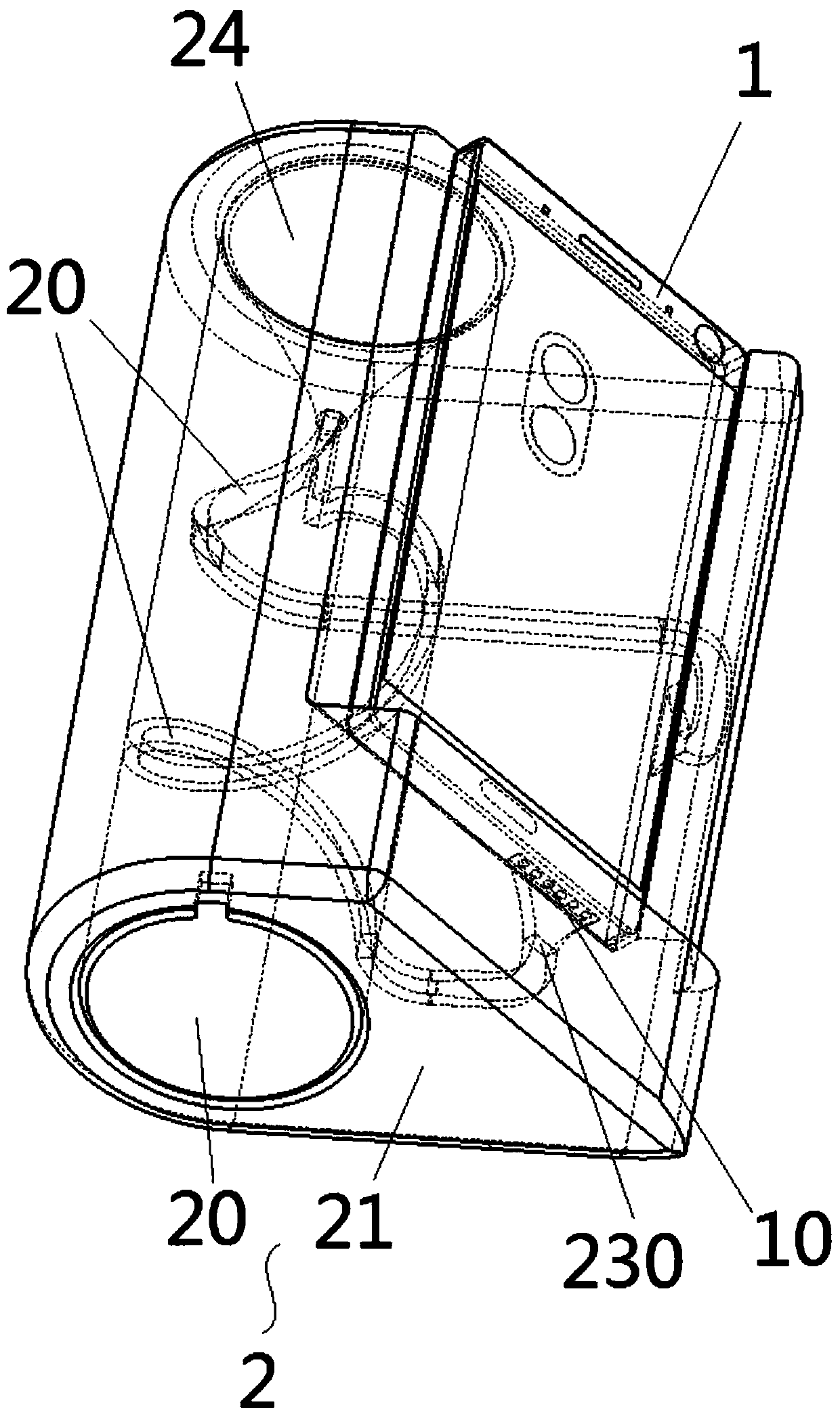
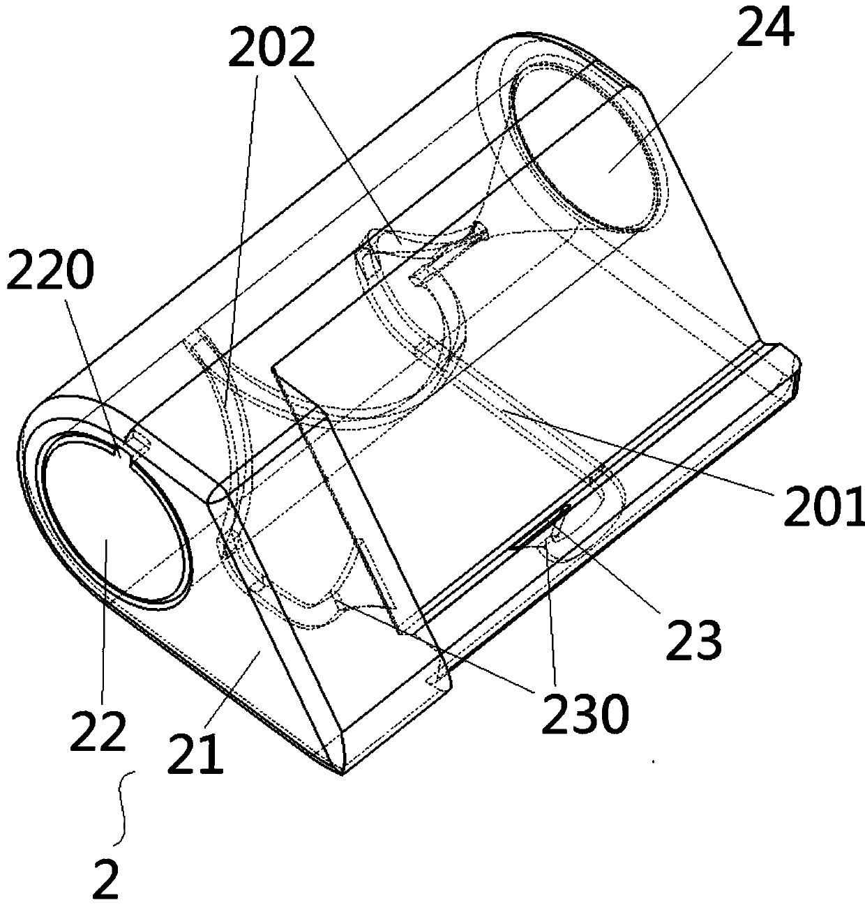
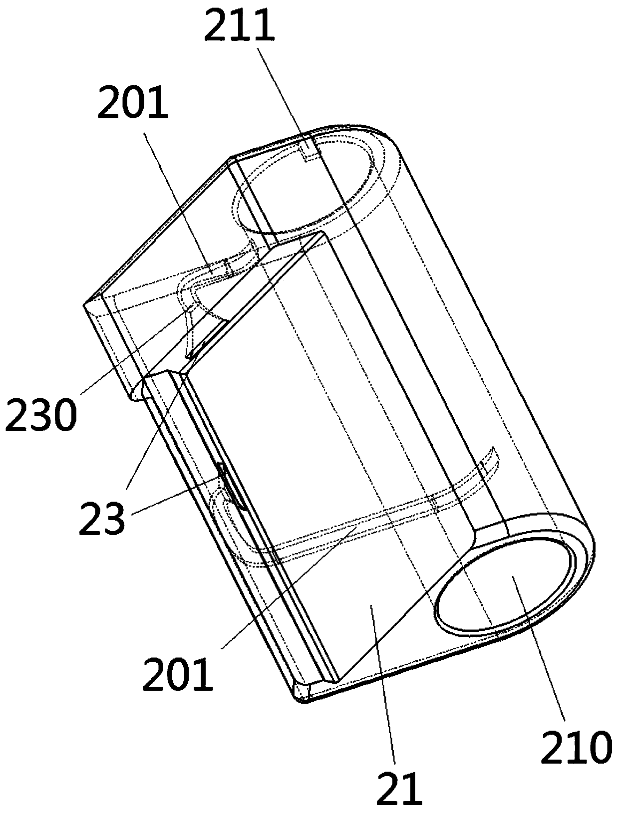
[0033] See attached figure 1 - attached Figure 10 , a kind of physical amplifying device, is used for mobile phone 1, and mobile phone 1 is provided with loudspeaker sound hole 10, and this physical amplifying device also comprises amplifying speaker 2, and amplifying speaker 2 is also provided with air cavity channel 20, and air cavity The channel 20 is divided into a sound inlet channel 201 and a sound outlet channel 202. The first end of the sound inlet c...


PUM


Abstract

ApPhysical sound amplifying device is disclosed. The device is applied to a mobile phone, the mobile phone is provided with a loudspeaker sounding hole; The physical sound amplification device also comprises a sound amplification sound box. the sound amplification box is also provided with an air cavity; the air cavity channel is divided into a sound inlet cavity channel and a sound outlet cavitychannel; The first end of the sound inlet cavity channel is a sound inlet, the sound inlet is tightly attached to a sound outlet hole of the loudspeaker, one end of the sound outlet cavity channel isconnected with the second end of the sound inlet cavity channel, the other end extends in the sound amplification box and penetrates through one outer wall of the sound amplification box, a sound outlet is formed in the penetrating position, a throat is formed between the first end and the second end of the sound inlet cavity channel, and the sound outlet is larger than the throat. The playing volume and the playing effect of the mobile phone loudspeaker can be effectively improved without power supply of a power supply.

Description

technical field [0001] The invention relates to the field of mobile phones, in particular to a physical loudspeaker device. Background technique [0002] With the development of science and technology, the functions of mobile phones are becoming more and more powerful, bringing more fun to people's lives. Mobile phones basically have music and video playback functions, so many people are used to turning on their mobile phones to enjoy a piece of music or music in their spare time. Video, however, on the one hand, because there is no special mobile phone holder, it can only be held in a handheld state when playing audio, which is relatively easy to fatigue and cannot free up hands to handle other things, which is not very convenient. On the other hand, it is generally through the mobile phone speaker The sounds that are emitted are relatively small and the effect is not good. The problem of mobile phone sound can be solved by wearing earphones or external speakers and other a...

Claims


Application Information

Patent Timeline
Patent Type & Authority Applications(China)
IPC IPC(8): H04M1/60G10K13/00
CPCG10K13/00H04M1/60Y02D30/70
Inventor 陈广
Owner GUANGZHOU ZHEXI CREATIVE DESIGN CO LTD
Learn More