Annular horizontal lifting device for iron sheet bucket

A technology of lifting device and iron bucket, which is applied in the direction of transportation and packaging, load hanging components, etc., can solve problems such as prone to falling accidents, and achieve the effect of preventing easy falling off and stable unloading

Inactive Publication Date: 2019-05-31
张进波
View PDF0 Cites 0 Cited by
  • Summary
  • Abstract
  • Description
  • Claims
  • Application Information

AI Technical Summary

Problems solved by technology

[0002] In the chemical industry, construction, food or industrial processing industries, many kinds of raw materials need to be used. Due to the large amount of use, iron barrels with larger capacity are usually used to hold the raw materials, and it is common for the equipment or place of use to be high. How to use It has always been a problem to deliver the metal drum from the bottom to the high place, the main reason is that the total weight of the metal drum and raw materials reaches more than 100 kg; figure 1 , the structure of the existing iron barrel is that the lower end of the annular barrel is formed by a circular iron sheet and the annular barrel by stacking and bending to form a circular lower outer bending thickened side (4) of one to two centimeters, and the upper end of the annular barrel is similar Another piece of circular iron sheet and the upper end of the annular cylinder are stacked and bent to form a circular upper and outer bent thickened edge (1) of one to two centimeters, and one or two barrel covers (2) are set on the upper circular iron sheet ) to form the barrel body (3) of the iron barrel. Since there is no place to grab or hook it when lifting, the current method is to use a rope to bind the middle part of the barrel (3) in order to safely deliver the iron barrel to a high place , the disadvantage of this approach is that it is prone to drop accidents when hoisting

Method used


Image

  • Annular horizontal lifting device for iron sheet bucket
  • Annular horizontal lifting device for iron sheet bucket
  • Annular horizontal lifting device for iron sheet bucket

Examples


Embodiment Construction

[0023] The present invention is further described below in conjunction with embodiment; The following embodiment is not for the limitation of the present invention, only as the mode of supporting the realization of the present invention, any equivalent structural replacement within the technical framework disclosed in the present invention, all is the present invention. the scope of protection of the invention;

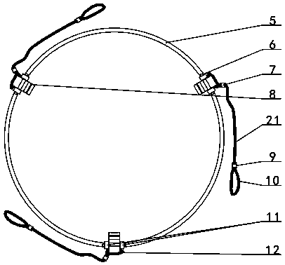
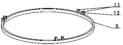
[0024] combined with Figures 2 to 5 The ring-shaped horizontal lifting device of the iron bucket includes a steel ring 5, a pin shaft 6, a block 8 and a suspension rope 21, and three connecting seats 11 in a triangular distribution are arranged on the upper surface of the steel ring 5. The connecting seat 11 is formed by two vertical plates, and the middle parts of the two vertical plates are provided with corresponding shaft holes A13. In the shaft hole A13 of the vertical plate; an arc-shaped depression 16 is provided on the upper surface close to the inner side o...


PUM


Abstract

The invention discloses an annular horizontal lifting device for an iron sheet bucket, and relates to a lifting device for an iron sheet raw material bucket. Three connecting bases (11) which are distributed in a triangular mode are arranged on the upper portion surface of a steel ring (5), the lower portion of a clamping block (8) is hinged to each connecting base through a pin shaft (6), the upper portion surface, close to the inner side, of each clamping block is provided with a circular-arc-shaped concave portion (16), the steel ring is arranged on the upper portion of a bucket body (3) ina sleeving mode at intervals, the circular-arc-shaped concave portions of the three clamping blocks abut against the lower portion surface of the outer edge of an upper outer bent thickened edge (1),the outer sides of the three clamping blocks are connected with the corresponding ends of lifting ropes (21), and the other ends of the three lifting ropes are connected with lifting appliances. According to the annular horizontal lifting device for the iron sheet bucket, the three clamping blocks are positioned to be of a triangular structure through the steel ring, the upper outer bent thickened edge of the bucket body is locked in three directions, and therefore the bucket body lifting stability is achieved.

Description

【Technical field】 [0001] The invention relates to a hoisting device for an iron-skin raw material barrel, in particular the invention relates to a ring-shaped horizontal hoisting device for an iron-skin barrel. 【Background technique】 [0002] In the chemical industry, construction, food or industrial processing industries, many kinds of raw materials need to be used. Due to the large amount of use, iron barrels with larger capacity are usually used to hold the raw materials, and it is common for the equipment or place of use to be high. How to use It has always been a problem to deliver the metal drum from the bottom to the high place, the main reason is that the total weight of the metal drum and raw materials reaches more than 100 kg; figure 1 , the structure of the existing iron barrel is that the lower end of the annular barrel is formed by a circular iron sheet and the annular barrel by stacking and bending to form a circular lower outer bending thickened side (4) of on...

Claims


Application Information

Patent Timeline
IPC IPC(8): B66C1/12B66C1/42
Inventor 张进波
Owner 张进波
Why Eureka
Try Eureka