A horizontal lifting device for an automatic locking iron bucket

A technology of lifting device and iron bucket, which is applied in the direction of safety device, transportation and packaging, load hanging components, etc., can solve the problems of prone to falling accidents, and achieve the effect of preventing easy falling off and stable unloading

Active Publication Date: 2020-12-29
闫传桂
View PDF7 Cites 0 Cited by
  • Summary
  • Abstract
  • Description
  • Claims
  • Application Information

AI Technical Summary

Problems solved by technology

[0002] In the chemical industry, construction, food or industrial processing industries, many kinds of raw materials need to be used. Due to the large amount of use, iron barrels with larger capacity are usually used to hold the raw materials, and it is common for the equipment or place of use to be high. How to use It has always been a problem to deliver the metal drum from the bottom to the high place, the main reason is that the total weight of the metal drum and raw materials reaches more than 100 kg; figure 1 , the structure of the existing iron barrel is that the lower end of the annular barrel is formed by a circular iron sheet and the annular barrel by stacking and bending to form a circular lower outer bending thickened side (4) of one to two centimeters, and the upper end of the annular barrel is similar Another piece of circular iron sheet and the upper end of the annular cylinder are stacked and bent to form a circular upper and outer bent thickened edge (1) of one to two centimeters, and one or two barrel covers (2) are set on the upper circular iron sheet ) to form the barrel body (3) of the iron barrel. Since there is no place to grab or hook it when lifting, the current method is to use a rope to bind the middle part of the barrel (3) in order to safely deliver the iron barrel to a high place , the disadvantage of this approach is that it is prone to drop accidents when hoisting

Method used


Image

  • A horizontal lifting device for an automatic locking iron bucket
  • A horizontal lifting device for an automatic locking iron bucket
  • A horizontal lifting device for an automatic locking iron bucket

Examples


Embodiment Construction

[0024] The present invention is further described below in conjunction with embodiment; The following embodiment is not for the limitation of the present invention, only as the mode of supporting the realization of the present invention, any equivalent structural replacement within the technical framework disclosed in the present invention, all is the present invention. the scope of protection of the invention;

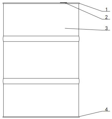
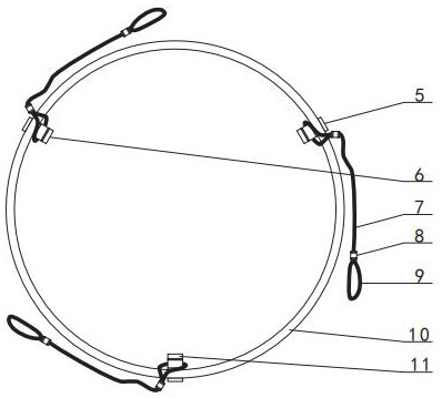
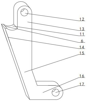
[0025] combined with Figures 2 to 6 The horizontal lifting device of the automatic locking iron bucket includes a collar 10, a pin shaft, a lock block 5 and a sling 7, and three through holes in a triangular distribution are arranged between the inner surface and the outer edge surface of the collar 10 20. The horizontal blocks 16 at the bottom of the three locking blocks 5 are respectively hinged to the through holes 20 of the collar 10 through pin shafts. The upper inner ends of the horizontal blocks 16 of the three locking blocks 5 are provided with an inclined bl...


PUM


Abstract

A horizontal lifting device for an automatic locking iron bucket, relating to a lifting device for an iron raw material bucket, in which three through holes (20) arranged in a triangular distribution are provided between the inner surface and the outer edge surface of a collar (10). The horizontal blocks (16) at the bottom of the first locking block (5) are respectively through the through holes of the collars hingedly connected by pin shafts. The upper inner ends of the horizontal blocks of the three locking blocks are provided with inclined blocks (15), and the upper ends of the inclined blocks are connected to the vertical blocks ( 13) The lower end is connected, and an inner protrusion (14) is provided in the middle of the inner side of the vertical block. The upper end of the inner protrusion is provided with a circular arc-shaped depression (11). One end is connected, and the other end of the three slings is connected to the sling; the present invention utilizes a collar to position the three lock blocks into a triangular structure, and the lock blocks on the barrel can automatically lock the barrel by their own weight. The upper and outer bent and thickened sides of the barrel body are locked to obtain stability when the barrel body is hoisted.

Description

【Technical field】 [0001] The invention relates to a hoisting device for an iron-skin raw material barrel, in particular the invention relates to a horizontal hoisting device for an automatic locking iron-skin barrel. 【Background technique】 [0002] In the chemical industry, construction, food or industrial processing industries, many kinds of raw materials need to be used. Due to the large amount of use, iron barrels with larger capacity are usually used to hold the raw materials, and it is common for the equipment or place of use to be high. How to use It has always been a problem to deliver the metal drum from the bottom to the high place, the main reason is that the total weight of the metal drum and raw materials reaches more than 100 kg; figure 1 , the structure of the existing iron barrel is that the lower end of the annular barrel is formed by a circular iron sheet and the annular barrel by stacking and bending to form a circular lower outer bending thickened side (4)...

Claims


Application Information

Patent Timeline
Patent Type & Authority Patents(China)
IPC IPC(8): B66C1/16B66C1/62
CPCB66C1/12B66C15/00
Inventor 李和庭
Owner 闫传桂
Why Eureka
Try Eureka