Lifting appliance for metal bucket

A technology of iron buckets and slings, applied in the direction of load hanging components, transportation and packaging, etc., can solve problems such as prone to falling accidents, and achieve the effect of preventing easy falling off

Inactive Publication Date: 2019-07-05
李和庭
View PDF4 Cites 0 Cited by
  • Summary
  • Abstract
  • Description
  • Claims
  • Application Information

AI Technical Summary

Problems solved by technology

[0004] In the chemical industry, construction, food or industrial processing industries, many kinds of raw materials need to be used. Due to the large amount of use, iron barrels with larger capacity are usually used to hold the raw materials, and it is common for the equipment or place of use to be high. How to use It has always been a problem to deliver the metal drum from the bottom to the high place, the main reason is that the total weight of the metal drum and raw materials reaches more than 100 kg; figure 1 , the structure of the existing iron barrel is that the lower end of the annular barrel is formed by a circular iron sheet and the annular barrel by stacking and bending to form a circular lower outer bending thickened side (4) of one to two centimeters, and the upper end of the annular barrel is similar Another piece of circular iron sheet and the upper end of the annular cylinder are stacked and bent to form a circular upper and outer bent thickened edge (1) of one to two centimeters, and one or two barrel covers (2) are set on the upper circular iron sheet ) to form the barrel body (3) of the iron barrel. Since there is no place to grab or hook it when lifting, the current method is to use a rope to bind the middle part of the barrel (3) in order to safely deliver the iron barrel to a high place , the disadvantage of this approach is that it is prone to drop accidents when hoisting

Method used


Image

  • Lifting appliance for metal bucket
  • Lifting appliance for metal bucket
  • Lifting appliance for metal bucket

Examples


Embodiment Construction

[0029] The present invention is further described below in conjunction with embodiment; The following embodiment is not for the limitation of the present invention, only as the mode of supporting the realization of the present invention, any equivalent structural replacement within the technical framework disclosed in the present invention, all is the present invention. the scope of protection of the invention;

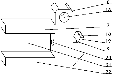
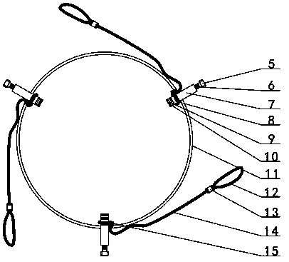
[0030] combined with Figures 2 to 6 The sling of the tin bucket includes a steel ring 11, a screw 5, a top block and a sling 14, and the steel ring 11 is provided with three screw holes 17 in a triangular distribution, on the outer surfaces of the three top blocks up and down. An upper clamping rod 7 and a lower clamping rod 22 are respectively provided, and the clamping groove 21 is formed between the upper clamping rod 7 and the lower clamping rod 22. Between the rod 7 and the lower clamping rod 22, the slots 21 on the outer sides of the three top blocks are respe...


PUM


Abstract

The invention discloses a lifting appliance for a metal bucket, and relates to a lifting device for a metal material bucket. Three screw holes (17) distributed in a triangle shape are arranged on a steel ring (11), clamping slots (21) in the outer side faces of three ejection blocks are clamped to the inner sides of the positions of all screw holes of the steel ring, the middle parts of screw rods(6) of three screws (5) are connected to the screw holes, the inner ends of the three screws eject the interiors of blind holes (20) in the groove bottoms of the clamping grooves of the three ejection blocks, the upper portions of the three ejection blocks are connected with one ends of lifting ropes (14), the upper portions of the inner ends of the three ejection blocks are provided with arc-shaped sinking parts (10), and the other ends of the three lifting ropes are connected with the lifting appliance. By means of the lifting appliance, the steel ring and the screws are used for positioning the three ejection blocks into a triangular structure, the upper outer bending thickening edge of a bucket body is locked in three directions, and stability during bucket lifting is obtained.

Description

[0001] 【Technical field】 [0002] The invention relates to a hoisting device for an iron-skin raw material barrel, in particular the invention relates to a sling for an iron-skin barrel. [0003] 【Background technique】 [0004] In the chemical industry, construction, food or industrial processing industries, many kinds of raw materials need to be used. Due to the large amount of use, iron barrels with larger capacity are usually used to hold the raw materials, and it is common for the equipment or place of use to be high. How to use It has always been a problem to deliver the metal drum from the bottom to the high place, the main reason is that the total weight of the metal drum and raw materials reaches more than 100 kg; figure 1 , the structure of the existing iron barrel is that the lower end of the annular barrel is formed by a circular iron sheet and the annular barrel by stacking and bending to form a circular lower outer bending thickened side (4) of one to two centimete...

Claims


Application Information

Patent Timeline
IPC IPC(8): B66C1/12
CPCB66C1/12
Inventor 李和庭
Owner 李和庭
Why Eureka
Try Eureka