Stone thrower toy

A technology of toys and stone carts, which is applied in the field of toys or props for scene simulation, can solve the problems of loose structure, inconvenience, and small elasticity, and achieve the effects of easy installation, increasing game fun, and exercising hands-on ability

Pending Publication Date: 2019-06-07
王闻博
View PDF0 Cites 2 Cited by
  • Summary
  • Abstract
  • Description
  • Claims
  • Application Information

AI Technical Summary

Problems solved by technology

[0003] However, most of the current catapult toys are made of wood and handmade. After a long time of use, the structure will become loose and affect the experience.
Moreover, most of the catapult toys are single-shot projectiles. Due to the structure itself, they can only hit targets in a fixed area. If you change the target, you need to move the catapult toy, which is very inconvenient.
Catapult toys on the market are mostly small structures with small elasticity, suitable for children. For big friends who want to experience, there is no better product to satisfy them

Method used


Image

  • Stone thrower toy
  • Stone thrower toy
  • Stone thrower toy

Examples


Embodiment 1

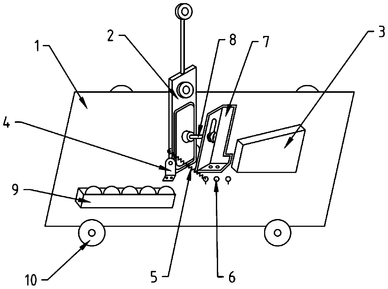
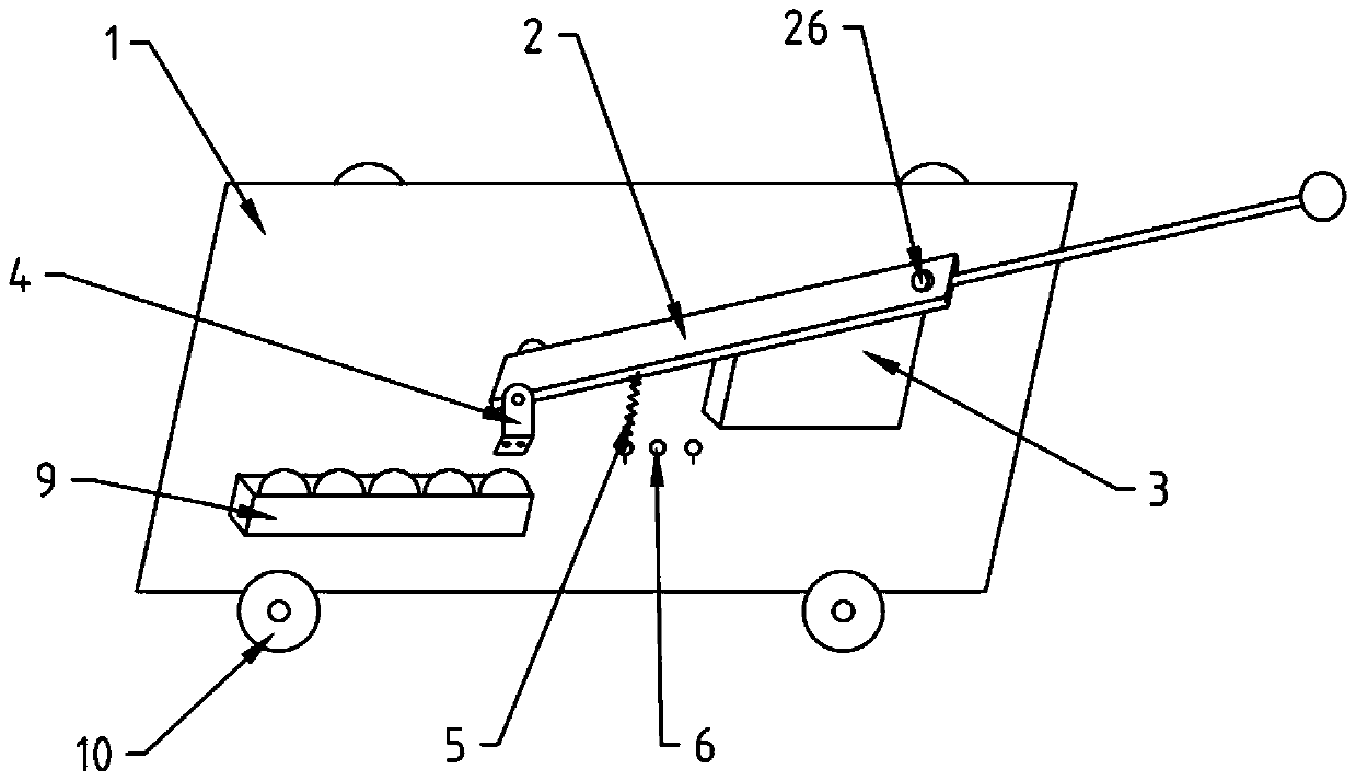
[0033] see figure 1 , figure 1 It is a kind of catapult toy of this embodiment, which comprises an underframe 1, a catapult arm 2, a front block 3 and a limit plate 7, and the catapult arm 2 is connected with a main catapult 23 and an auxiliary catapult 25, and the catapult arm 2 is connected with the fixed plate 4 on the bottom frame 1 through the rotating shaft, and can rotate freely around the rotating shaft. The side of the catapult arm 2 is connected with the pull ring 6 on the bottom frame 1 through the first spring 5. A detachable limit plate 7 is arranged between them, and a locking device 8 is installed on the limit plate 7, which can limit the stop position of the catapult arm 2 after it bounces up.

[0034] Combine below Figure 4 , in this embodiment, the sling arm 2 includes a sling 21, a rubber pad 22, a main sling 23, a telescopic rod 24 and an auxiliary sling 25, wherein the rubber pad 22 is located at the middle and lower part of the sling 21 for Buffer the...

Embodiment 2

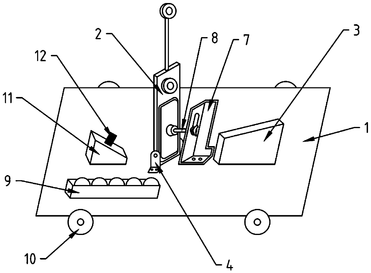
[0052] see image 3 , different from Embodiment 1, this embodiment is provided with an inclined rear stopper 11 at the rear end of the catapult arm 2, and a second spring 12 is provided at the middle position on it to provide elastic force for the catapult arm 2 to launch ammunition, and the installation on the The first spring 5 and the pull ring 6 on the side of the throwing arm 1.

[0053] Further, the upper end surface of the rear stopper 11 is an inclined plane, and the inclination angle is the same as the angle at which the catapult arm 2 rotates to the position of the rear stopper 11 .

[0054] This embodiment is mainly suitable for children with less strength. Because in Embodiment 1, the first spring 5 needs to be pulled back hard. For children with less strength, they cannot play without pulling the first spring 5. This embodiment During operation, it is only necessary to press down firmly after loading the ammunition on the catapult arm 2, which is more convenient ...


PUM


Abstract

The invention discloses a stone thrower toy which comprises a bottom frame (1), a stone throwing arm (2), a front stop block (3) and a limiting plate (7). A main stone throwing hopper (23) and an auxiliary stone throwing hopper (25) are connected to the stone throwing arm (2). The stone throwing arm (2) is connected with a fixing plate (4) on the base frame (1) through a rotating shaft and can rotate freely around the rotating shaft, the side face of the stone throwing arm (2) is connected with one pull ring (6) on the base frame (1) through a first spring (5), the detachable limiting plate (7) is arranged between the stone throwing arm (2) and the front stop block (3), and a locking device (8) is installed on the limiting plate (7) and can limit the stop position formed after the stone throwing arm (2) is bounced. According to the stone thrower toy, multiple times of throwing can be performed, and the length and the initial velocity of the stone throwing arm (2) can be regulated, so that the range is changed, operability and flexibility are achieved, and the audience is wider.

Description

technical field [0001] The invention relates to a scene simulation toy or prop, in particular to a catapult toy. Background technique [0002] The catapult first appeared in the Warring States period. It is an ancient weapon of war. It uses the principle of leverage. There is a fixed horizontal axis between the two pillars of the frame, and there is a lever perpendicular to the axis. It can rotate freely around the axis and can pass heavy objects or The elastic force sends stone bullets or other ammunition far away. Later, this kind of war weapon was made into a small toy for children to play, and it can also inspire interest in physics learning. [0003] However, most of the current catapult toys are made of wood. After a long time of use, the structure will become loose and affect the experience. Moreover, most of the catapult toys are single-shot projectiles. Due to the structure itself, they can only hit targets in a fixed area. If you change the target, you need to mo...

Claims


Application Information

Patent Timeline
Patent Type & Authority Applications(China)
IPC IPC(8): A63H33/18
Inventor 王闻博
Owner 王闻博
Why Eureka
Try Eureka