A table top splicing device

A technology of splicing device and table board, applied in the field of table furniture, can solve the problems of inconvenient installation, insufficient connection strength, complex structure, etc., and achieve the effect of stable connection and large contact surface

Active Publication Date: 2022-06-17
UE FURNITURE CO LTD
View PDF9 Cites 0 Cited by
  • Summary
  • Abstract
  • Description
  • Claims
  • Application Information

AI Technical Summary

Problems solved by technology

[0006] But this type of structure also has an obvious disadvantage: that is, the connection strength is not enough, and the two boards are only supported by the plug-in part. If one of the boards is pressed hard, the board will sink relative to the other board under force. There is a height difference between the other boards, that is, the uniform force cannot be guaranteed, and the connection stability cannot be guaranteed
This structure makes the entire edge of one of the plates closely bonded to the entire edge of the other plate to ensure the connection strength of the joint; If the place is small and the inside is large, it is necessary to align the splicing protrusions with the splicing grooves and slide a large distance along the width direction to complete the splicing; although it can be disassembled and packaged for transportation, it is not convenient for users to install by themselves, which makes consumers experience poor
[0008] Another thing is to use the rotating method to realize the splicing between the table boards. The two table boards are rotated and connected together through the rotating shaft or the hinge, and then the rotating connection of the two table boards is provided with a plug-in structure; After the boards are flipped and unfolded, the two table boards are spliced ​​together under the action of the plug-in structure; although the structure is relatively stable and the operation is convenient; The desktop is not beautiful, and it can be clearly seen that it is a splicing structure, which affects its shape

Method used


Image

  • A table top splicing device
  • A table top splicing device
  • A table top splicing device

Examples


specific Embodiment approach

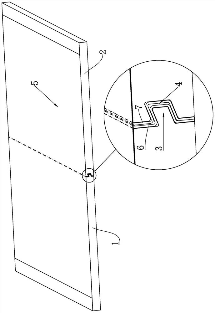
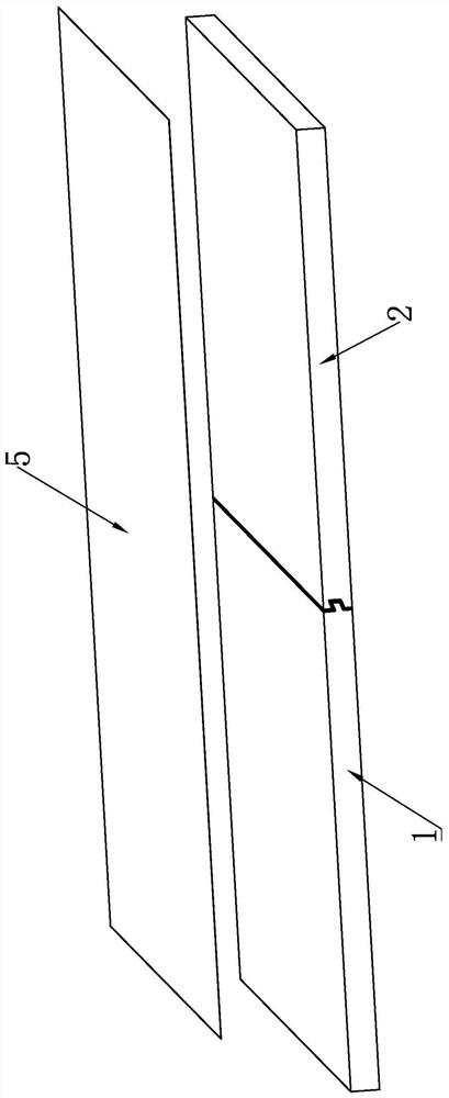
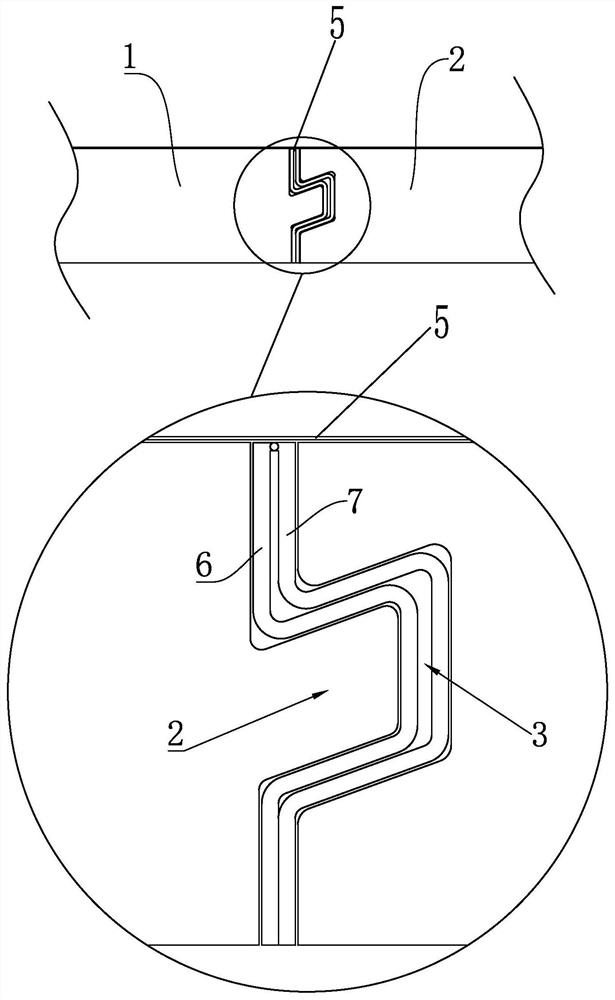
[0044] like Figure 1-7 As shown, the present invention provides a table board splicing device, which includes: splicing table boards, and the splicing table boards includes adjacent first splicing boards 1 and second splicing boards 2 . A splicing mechanism is provided between the first splicing plate 1 and the second splicing plate 2 , and the splicing mechanism includes splicing protrusions 3 arranged on the side of the first splicing plate 1 and correspondingly arranged on the side of the second splicing plate 2 On the splicing groove 4, the splicing protrusion 3 can be snapped into the splicing groove 4 to make the first splicing board 1 and the second splicing board 2 spliced ​​to form a desktop; wherein the first splicing board 1 and the second splicing board 2 Having an upper surface and a lower surface, the side edges refer to the sides located on either side of the splice plate and formed between the upper and lower surfaces. It also includes a hinge mechanism that ...


PUM


Abstract

The invention discloses a table splicing device, which comprises a splicing table, the splicing table includes a first splicing plate and a second splicing plate; The splicing protrusion and the splicing groove; the hinge mechanism is configured to enable the first splicing plate and the second splicing plate to be turned over; The veneer layer; and the first edge banding arranged on the outer surface of the splicing protrusion and the second edge banding arranged on the inner surface of the splicing groove; the first edge banding and the second edge banding are connected together, the The joint has ductility so that the first edge strip and the second edge strip can rotate each other; during packaging and transportation, the first splicing plate and the second splicing plate are turned over and stacked together; The first splicing board and the second splicing board are turned over and unfolded, and the splicing protrusions are snapped into the splicing grooves at the same time.

Description

technical field [0001] The invention relates to the field of table furniture, in particular to a table board splicing device. Background technique [0002] In order to meet the current trend of e-commerce, the products sold online need to be delivered to customers by logistics, so the transportation cost of the products will increase, and the convenience of packaging and transportation and reducing the cost of packaging and transportation will bring higher costs for companies and manufacturers benefit. As for the table board of the table, a single table board is heavy, it is not easy to package and transport, and it is not conducive to allocating the space occupied during transportation. Therefore, many tables on the market now divide the table board into multiple small table boards. The table top is formed by splicing, thereby solving the above problems; in addition, the splicing structure between the small table boards after the table board is divided can be adopted in va...

Claims


Application Information

Patent Timeline
Patent Type & Authority Patents(China)
IPC IPC(8): A47B13/08
CPCA47B13/08A47B13/086
Inventor 俞鹏飞虞红潮王科亭
Owner UE FURNITURE CO LTD
Why Eureka
Try Eureka