Supporting tool for machining and method for machining tensioning sleeve by using supporting tool

A technology of tensioning sleeves and expansion sleeves, which is applied in the direction of manufacturing tools, metal processing equipment, and machine tools designed for grinding the rotating surface of workpieces. and shape and position tolerances, etc., to reduce deformation, reduce the magnitude of deformation, and improve the effect of use

Active Publication Date: 2019-06-07
无锡高晟成型科技有限公司
View PDF7 Cites 8 Cited by
  • Summary
  • Abstract
  • Description
  • Claims
  • Application Information

AI Technical Summary

Problems solved by technology

[0004] Aiming at the problems that the existing processing tensioning sleeve is prone to large deformation, the amount of deformation is difficult to control, the dimensional accuracy and shape tolerance cannot be accurately controlled, which affects the use effect and increases the production cost, the invention provides a processing brace, which It can not only effectively control the deformation direction and deformation amount, but also reduce the deformation amplitude, so as to accurately control the dimensional accuracy and shape tolerance of the tension sleeve, and also ensure that the concentricity and circular runout accuracy of the tension sleeve meet the requirements of the working condition. Requirements, effectively reduce the production cost, and improve the use effect of the tension sleeve, for this reason, the present invention also provides a method for processing the tension sleeve by using the brace

Method used


Image

  • Supporting tool for machining and method for machining tensioning sleeve by using supporting tool
  • Supporting tool for machining and method for machining tensioning sleeve by using supporting tool
  • Supporting tool for machining and method for machining tensioning sleeve by using supporting tool

Examples


Embodiment Construction

[0035] Below in conjunction with accompanying drawing, the present invention will be further described:

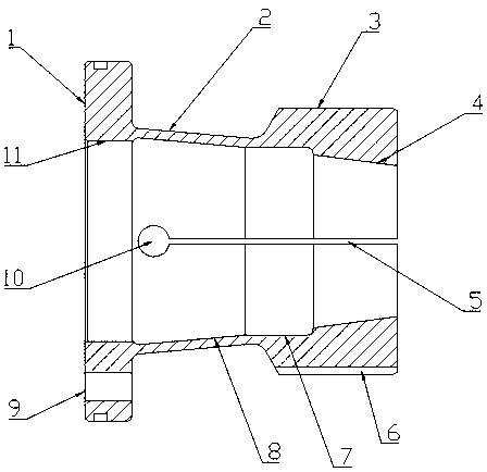
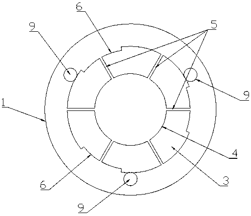
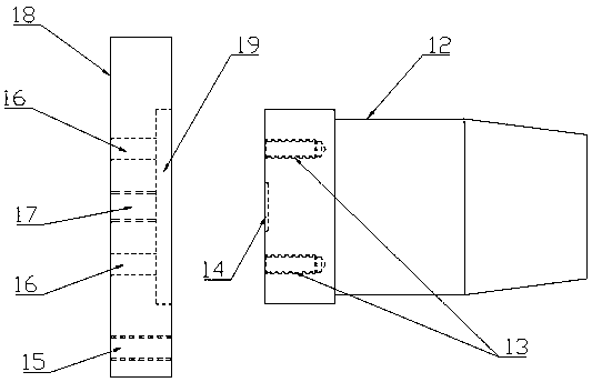
[0036] Such as Figure 1~6 As shown, the present invention provides a brace for processing, which includes a base 18 and a support body 12. The end surface of the base 18 is provided with a mounting groove 19. After the support body 12 is inserted into the mounting groove 19, a screw ( not shown) connection, at the central axis where the base 18 and the support body 12 are connected, the base 18 is provided with a threaded through hole 17, corresponding to the port of the threaded through hole 17, and the support body 12 is provided with a groove 14, preferably, as Figure 3~5 As shown, the support body 12 is provided with four blind holes 13, and the blind holes 13 are evenly distributed in a ring around the groove 14, and the base 18 is provided with threaded holes 16 corresponding to the blind holes 13, and screws (not shown) pass through The threaded via holes and bli...


PUM


Abstract

The invention provides a supporting tool for machining and a method for machining a tensioning sleeve by using the supporting tool. The supporting tool comprises a base and a supporting body, an installing groove is formed in the end face of the base, the supporting body is inserted behind the installing groove, the supporting body and the installing groove are connected through screws, a threadedthrough hole is formed in the center shaft and at the position of a center axis where the base and the supporting body connect, and a groove is formed in the supporting body and corresponds to the threaded through hole. In the machining process, the supporting tool internally supports the interior of the tensioning sleeve intermediate, the tensioning sleeve intermediate is changed into a workingstate from a natural state to be further machined, the deformation direction and the deformation amount can be effectively controlled, the deformation range is reduced, so that the dimensional precision and the form and location tolerance of the tensioning sleeve can be accurately controlled; and the concentricity, the coaxiality and the circular runout precision of the tensioning sleeve under theworking state can be ensured, the production cost is effectively reduced, and the using effect of the tensioning sleeve is improved.

Description

technical field [0001] The invention relates to the technical field of metal processing, in particular to a processing brace and a method for processing a tensioning sleeve using the brace. Background technique [0002] Tension sleeves are generally used to connect cylindrical inner hole parts in rotating machinery structures, and their structures are as follows figure 1 and figure 2 As shown, it includes a coaxial and connected installation chassis 1, a connecting sleeve 2 and an outer circular expansion sleeve 3. The inner hole of the outer circular expansion sleeve 3 is a conical surface 4, and cable grooves 5 are evenly distributed along the circumference of the expansion sleeve. The tensioning sleeve connects and fixes the cylindrical inner hole parts through the expansion sleeve 3 of the outer circle, and rotates together with the cylindrical inner hole parts to ensure the normal operation of the cylindrical inner hole parts. At this time, the tensioning sleeve is in...

Claims


Application Information

Patent Timeline
Patent Type & Authority Applications(China)
IPC IPC(8): B21D31/04B24B5/04B24B5/06B24B41/06B23P15/00
Inventor 周勋杰
Owner 无锡高晟成型科技有限公司
Why Eureka
Try Eureka