
A Quality Control Method for Laser Shot Peening Correction for Aeroengine Brackets

A quality control method and aero-engine technology, applied in laser welding equipment, manufacturing tools, welding equipment, etc., can solve problems such as deformation of aero-engine bracket welding process, achieve good correction effect, reduce welding deformation, and save materials.

Active Publication Date: 2018-03-23
GUANGDONG UNIV OF TECH
View PDF8 Cites 0 Cited by
  • Summary
  • Abstract
  • Description
  • Claims
  • Application Information

AI Technical Summary

Problems solved by technology

[0005] In view of this, the purpose of the present invention is to provide a method for quality control of laser shot peening correction of aero-engine brackets, which is used to solve the problem of deformation during the welding process of aero-engine brackets

Method used


Image

  • A Quality Control Method for Laser Shot Peening Correction for Aeroengine Brackets
  • A Quality Control Method for Laser Shot Peening Correction for Aeroengine Brackets
  • A Quality Control Method for Laser Shot Peening Correction for Aeroengine Brackets

Examples


Embodiment Construction

[0023] The core of the present invention is to provide a laser shot peening shape correction quality control method for an aero-engine bracket, which is used to solve the problem of deformation during the welding process of the aero-engine bracket.

[0024] The following will clearly and completely describe the technical solutions in the embodiments of the present invention with reference to the accompanying drawings in the embodiments of the present invention. Obviously, the described embodiments are only some, not all, embodiments of the present invention. Based on the embodiments of the present invention, all other embodiments obtained by persons of ordinary skill in the art without making creative efforts belong to the protection scope of the present invention.

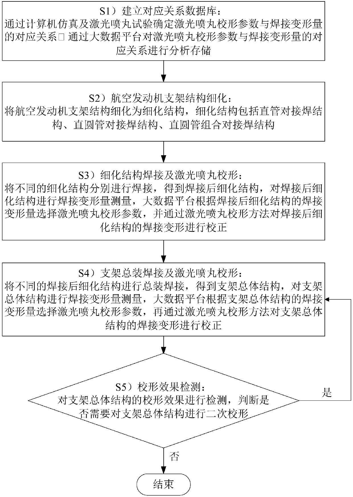
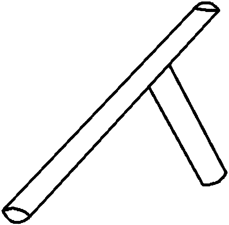
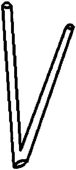
[0025] Please refer to Figures 1 to 5 , figure 1 It is a flow chart of the quality control method for laser peening shape correction in a specific embodiment of the present invention, Figure 2 to Figure 5 It i...


PUM


Abstract

The invention discloses a quality control method for laser shot peening shape correction for aero-engine brackets. ; Refinement structure welding and laser shot peening shape correction; bracket assembly welding and laser shot peening shape correction; shape correction effect detection. This scheme refines the complex aero-engine bracket into three simple thinning structures, and adopts the processing sequence of segmental welding, segmental laser shot peening, final assembly welding, and final assembly laser shot peening. The laser shot peening shape correction of the structure before the final assembly welding can reduce the welding deformation of the overall structure of the bracket, so that the overall structure of the bracket is easier to correct in the laser shot peening shape correction. The invention solves the problem of deformation of the aero-engine bracket during the welding process, can accurately control the size accuracy and shape accuracy of the bracket, and has good correction effect.

Description

technical field [0001] The invention relates to the field of aviation component manufacturing, in particular to a laser shot peening quality control method for aircraft engine brackets. Background technique [0002] The aircraft engine support is a space frame structure obtained by welding hollow steel pipes. During the welding process of the support nodes, the base metal is locally heated unevenly, which is prone to welding residual stress, causing large residual deformation of the space frame structure, and the shape accuracy is low. Poor, causing the mounting bolts of the engine bracket to deviate from the installation position, which affects the subsequent assembly. At present, the method used in practical engineering applications is to increase the size, and then use machining to cut off the excess deformation. This method is time-consuming and labor-intensive, and the processing consistency is poor. [0003] At present, the existing shape correction method is to repea...

Claims


Application Information

Patent Timeline
Patent Type & Authority Patents(China)
IPC IPC(8): B23K31/12B23K26/356
CPCB23K31/125B23K26/356B23K31/003C21D10/005
Inventor 张永康苏波勇张永俊
Owner GUANGDONG UNIV OF TECH
Learn More