Semiconductor microphone chip

A microphone and semiconductor technology, applied in the field of condenser microphone chips

Active Publication Date: 2008-01-02
GOERTEK MICROELECTRONICS CO LTD
View PDF3 Cites 23 Cited by
  • Summary
  • Abstract
  • Description
  • Claims
  • Application Information

AI Technical Summary

Problems solved by technology

[0004] The purpose of the present invention is to solve the problems existing in the existing microphone chip technology, mainly aiming at the problem of how to release the residual stress in the diaphragm and the stress concentration of the suspension beam structure, and proposes a diaphragm with a corrugated suspension beam structure, the diaphragm and capacitive structure formed by the back electrode

Method used


Image

  • Semiconductor microphone chip
  • Semiconductor microphone chip
  • Semiconductor microphone chip

Examples


Embodiment Construction

[0028] The present invention has many different forms of embodiments, and the accompanying drawing shows a preferred example of the present invention, which will be described in detail.

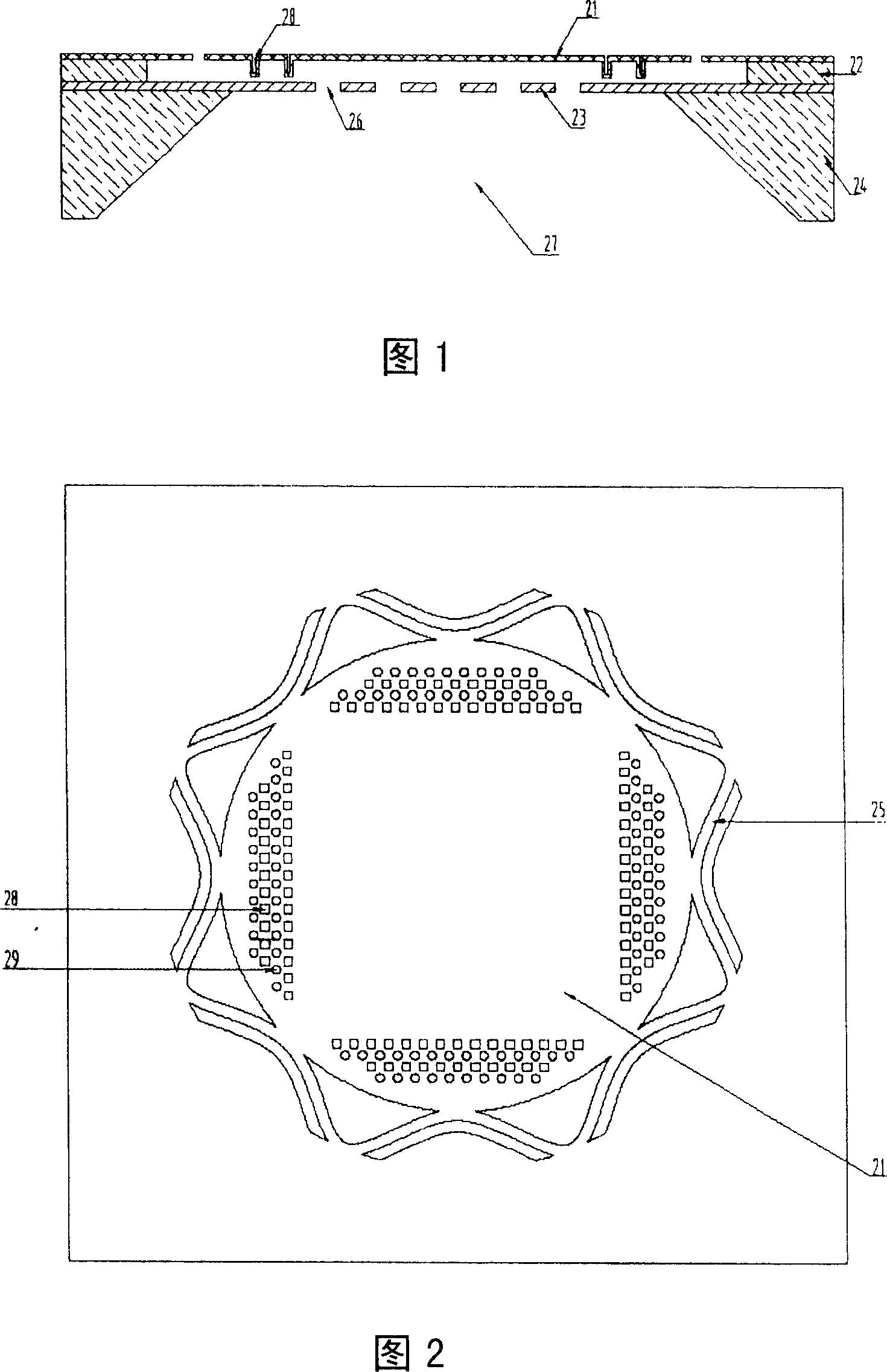
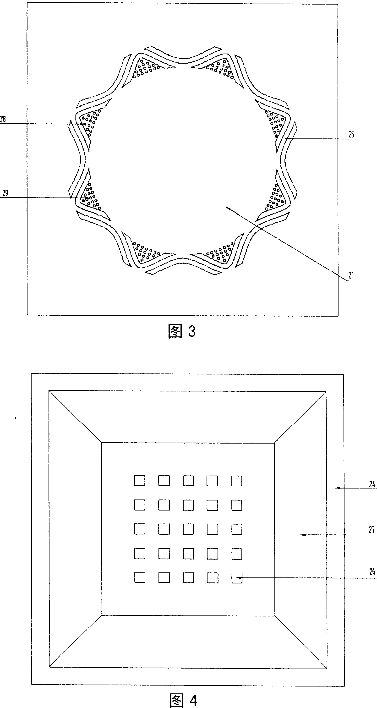
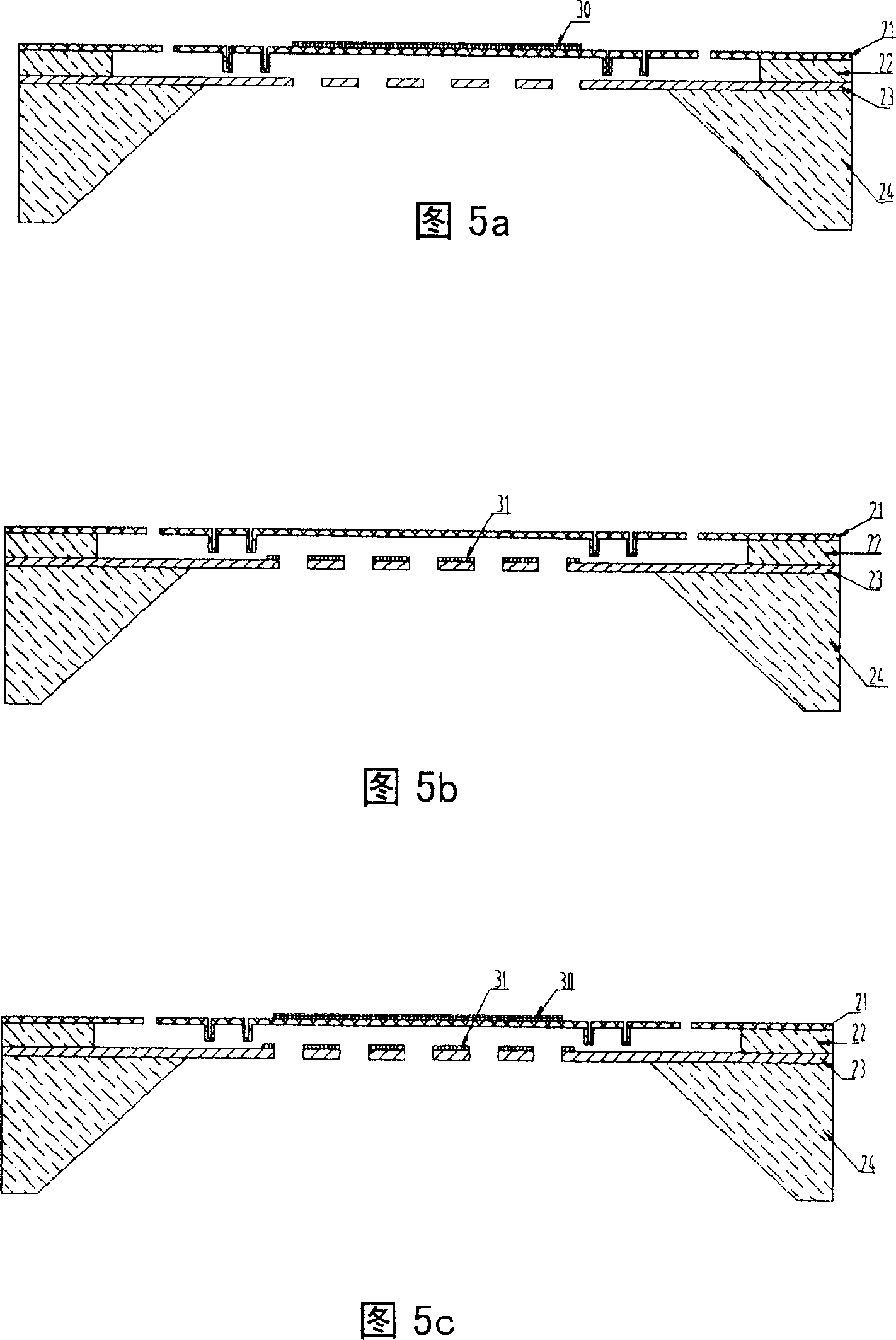
[0029] As shown in FIG. 1 , it is a condenser microphone chip of the present invention, and its structure includes: a diaphragm 21 , a support 22 , a back pole 23 , and a base 24 from top to bottom. The diaphragm 21 and the back pole 23 are made of conductive materials to form a capacitor structure; the diaphragm 21 is connected to the support 22 through a corrugated suspension beam 25 (see Fig. 2 and Fig. 3 ); the back pole 23 has an acoustic hole 26; the center of the base 24 has The back cavity 27 and the sound hole 26 are located within the range of the back cavity 27 .

[0030] As shown in FIG. 2 , the diaphragm 21 is connected to the frame and the support 22 through the suspension beam 25 , the suspension beam 25 has a corrugated structure, and the diaphragm 21 has a circular structure....


PUM


Abstract

The invention relates to a semi-conductor microphone chip, belonging to microphone chip technique, as one capacitor structure which vibration membrane is above and back pole is below, wherein the vibration membrane via a waveform beam is connected with a frame and a support to completely release the left stress of the vibration membrane, the vibration membrane is provided with a plurality of array micro concaves to support the vibration membrane and reduce sound leakage, the vibration membrane is provided with a plurality of holes, to engage with the sound holes on the back pole in the microphone chip preparation to release a sacrificial layer between the vibration membrane and the back pole. The invention has high flexibility, low noise, and wide frequency band, while the produced chip has small volume, simple preparation and batch production.

Description

technical field [0001] The invention relates to the technical field of microphone chips, in particular to a capacitive microphone chip with a diaphragm that reduces residual stress. Background technique [0002] In 1983, Royer produced the first microphone on a silicon chip, which attracted attention from all walks of life. Various types of microphones have been developed and implemented on silicon chips one after another. Among them, the most important and popular one is the condenser silicon microphone. The capacitive silicon micro microphone not only has the characteristics of small size, high sensitivity, good frequency response characteristics, and low noise, but more importantly, it has a wide operating temperature, which can be applied to SMT and other automated production lines and harsh working environments. It is currently any It cannot be replaced by a microphone, and it will open up a wider application space of the microphone. [0003] The condenser microphone...

Claims


Application Information

Patent Timeline
Patent Type & Authority Applications(China)
IPC IPC(8): H04R19/01H04R19/04
CPCH04R19/005H04R19/016H04R19/04
Inventor 宋青林梅嘉欣陶永春
Owner GOERTEK MICROELECTRONICS CO LTD
Why Eureka
Try Eureka