Low-speed diesel engine frame welding method

A welding method and diesel engine technology, applied in welding equipment, engine frames, supporting machines, etc., can solve problems such as asymmetric deformation, and achieve the effects of improving welding quality, solving deformation problems, and reducing filling amount.

Inactive Publication Date: 2003-03-26
HUDONG HEAVY MACHINERY +1
View PDF0 Cites 22 Cited by
  • Summary
  • Abstract
  • Description
  • Claims
  • Application Information

AI Technical Summary

Problems solved by technology

[0006] 1. Solve the problem of asymmetric deformation caused by the symmetrical groove of the weldment;

Method used


Image

  • Low-speed diesel engine frame welding method
  • Low-speed diesel engine frame welding method
  • Low-speed diesel engine frame welding method

Examples


Embodiment Construction

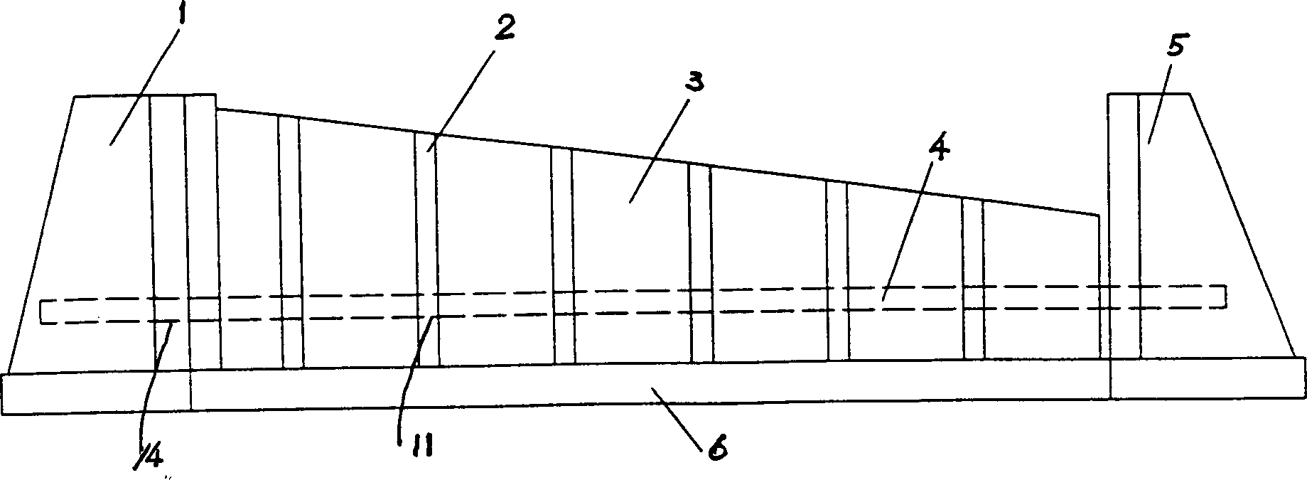
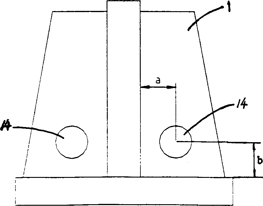
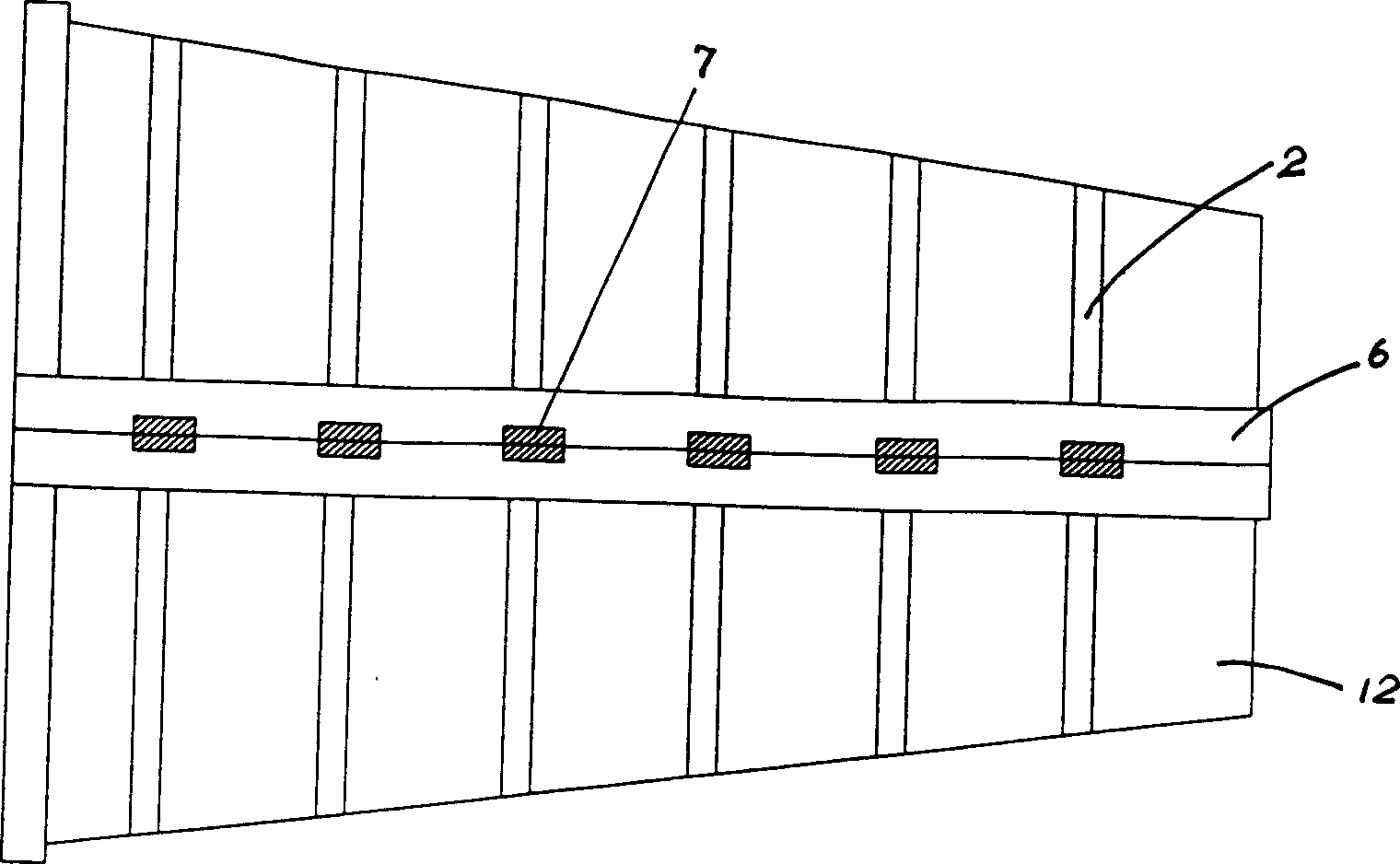
[0044] The welding method of the present invention will be further described with reference to the accompanying drawings. see first figure 1 , figure 2 and image 3 . The welding method of the low-speed diesel engine frame of the present invention comprises the following steps:

[0045] ① Use the positioning iron pipe 4 to pass through the through screw hole 11 of the small rib plate 2 and the through screw positioning holes 14 of the tire frames 1 and 5, and place multiple small rib plates 2 between the tire frame 1 and the tire frame 2 according to the design requirements Reasonable positioning, and spot welding on the guide plate 6 and the triangular plate 3 to form the guide plate part 12, such as figure 1 As shown, the structure of the tire frame is as follows figure 2 shown;

[0046] ② The guide plate parts 12 of the small rib plate 2 positioned symmetrically on the left and right are symmetrically brought together, and are welded and positioned with the strap ...


PUM


Abstract

A method for welding the frame of a low speed diesel engine. It includes the following steps: 1) By passing locating iron pipes through the screw holes in small iron plates, a number of small iron paltes are located between two bed-jigs according to the requirements of design, and spot welded on a guide plate and a triangle plate to form guide plate components. 2) The bilateral symmetric and located guide plate components are put symmetrically side by side and located by butt strap welding. 3) The welded and located bilateral guide plate component are welded in symmetry. 4) After welding, butt straps are removed, and the bila-teral guide plate components are separated. 5) with the help of the bed-jig, the bilateral guide plate components and a division plate are located on a cast-iron platform.

Description

Technical field: [0001] The invention relates to a low-speed diesel engine and relates to a welding method, in particular to a welding method for a frame of a low-speed diesel engine. Background technique: [0002] The local space of the diesel engine frame is small, but the requirements for the welding seam are high, welding and cleaning are difficult, and the welding deformation is difficult to control. The welding process of the existing diesel engine frame is as follows: Figure 7 and Figure 8 as shown, Figure 7 It is a schematic diagram of existing symmetrical groove welding. After welding 1-2 layers on the front side, and then welding on the back side, carbon planing must be carried out before welding, so that the actual welding position on the back side exceeds the center line, resulting in asymmetric deformation. It is difficult to control the deformation. Therefore, the amount of deformation does not meet the specified requirements. [0003] Figure 8 Is the sc...

Claims


Application Information

Patent Timeline
Patent Type & Authority Applications(China)
IPC IPC(8): B23K31/02F16M1/08
Inventor 王敏时洪星李晓东
Owner HUDONG HEAVY MACHINERY
Why Eureka
Try Eureka