Demolding device, injection mold and injection molding workpiece demolding method

A demoulding device and workpiece technology, which is applied in the field of injection molding, can solve the problems of long demoulding cycle, low production efficiency, and difficult demoulding of injection molded workpieces, and achieve the effect of simplifying demoulding steps and avoiding damage

Active Publication Date: 2019-07-02
SHENZHEN MEIHAO CHUANGYI MEDICAL TECH
View PDF4 Cites 0 Cited by
  • Summary
  • Abstract
  • Description
  • Claims
  • Application Information

AI Technical Summary

Problems solved by technology

[0004] The invention provides a demoulding device, an injection mold and a demoulding method for injection molded workpieces, which are used to solve the problems of difficult demoulding from injection molded workpieces, long demoulding cycle and low production efficiency in the prior art

Method used


Image

  • Demolding device, injection mold and injection molding workpiece demolding method
  • Demolding device, injection mold and injection molding workpiece demolding method
  • Demolding device, injection mold and injection molding workpiece demolding method

Examples


Embodiment Construction

[0028] In order to make the object, technical solution and advantages of the present invention more clear, the present invention will be further described in detail below in conjunction with the accompanying drawings and embodiments.

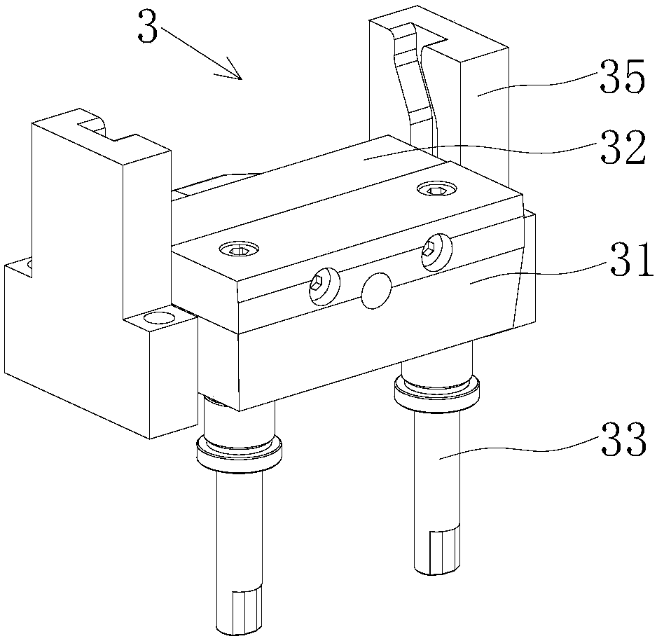
[0029] It should be noted that, in this specification, the ejection direction of the ejector rod is defined as the "upper" direction, and the sliding direction of the push block relative to the ejector block is defined as the "front" direction.

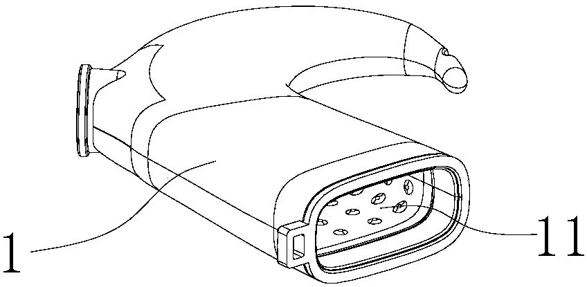
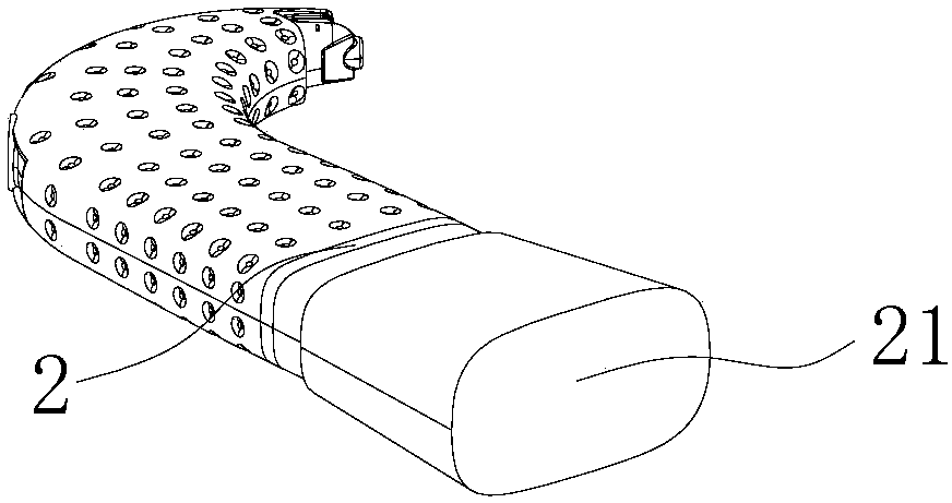
[0030] refer to figure 1 , figure 2 , the first embodiment of the present invention provides an injection mold for molding an injection molded workpiece 1, the injection molded workpiece 1 has an inner cavity 11, the inner cavity 11 is formed by a core 2, and the core 2 has a The core-pulling end 21 of the cavity 11 opening.

[0031] The injection mold includes a movable mold (not shown in the figure), a fixed mold (not shown in the figure) and a core 2. After the movable mold and the fixed mold are ...


PUM


Abstract

The invention provides a demolding device suitable for demolding an injection molding workpiece with an inner cavity. The demolding device comprises an ejector block, a push block and ejector rods. The ejector block comprises an ejection part and an installation part, and the size of the installation part decreases gradually from back to front. The push block is provided with an accommodating hole, and the structure of the accommodating hole is identical with the external structure of the installation part. After the installation part penetrates into the accommodating hole from the rear end, the front end of the accommodating hole is used for fixing a mold core used for forming the inner cavity of the injection molding workpiece. After the injection molding workpiece is molded outside themold core, the injection molding workpiece completely closes the front end opening of the accommodating hole. The ejector rods are arranged below the ejection part and used for pushing the ejector block and the push block to move upward. The push block can also move forward relative to the ejector block to form a ventilation gap between the accommodating hole and the outer wall of the installationpart. A ventilation cavity penetrating into the ventilation gap from the rear end of the ejection part is further arranged in the ejector block and ventilates the interior of the ejector block, the gas exerts pressure on the injection molding workpiece, and thus the injection molding workpiece is separated from the mold core. The invention further provides an injection mold and an injection molding workpiece demolding method.

Description

technical field [0001] The invention relates to the technical field of injection molding, in particular to a demoulding device, an injection mold and a demoulding method for an injection molded workpiece. Background technique [0002] There are usually two demoulding methods for injection molded workpieces with inner cavity structure: the first is to pull the core that forms the inner cavity structure of the injection molded workpiece, and then demould; the second is to first remove the molded workpiece-core The structural part is removed from the mold and the injection molded part is demoulded from the core. For the second demoulding method, when the inner cavity of the injection molded workpiece is deep, it is difficult to automatically fall off or brush off, so manual demoulding is usually required. However, for thermosetting injection molding parts, the surface temperature of the injection molding parts is high after the mold is opened, and it is difficult to remove the...

Claims


Application Information

Patent Timeline
Patent Type & Authority Applications(China)
IPC IPC(8): B29C45/33B29C45/44B29C45/43
CPCB29C45/332B29C45/435B29C45/44B29C2045/445B29C2045/4492
Inventor 林桂典周道福朱瀚吴华
Owner SHENZHEN MEIHAO CHUANGYI MEDICAL TECH
Why Eureka
Try Eureka