Manufacturing method of adhesive type iron core of motor

A manufacturing method and iron core technology, applied in the direction of manufacturing stator/rotor body, etc., can solve the problems of increased workload, limited adhesive force, increased labor intensity, etc., and achieve reduced precision requirements, less cracking between sheets, and shortened manufacturing. effect of cycles

Active Publication Date: 2012-06-27
XIANGTAN ELECTRIC MFG CORP LTD
View PDF0 Cites 0 Cited by
  • Summary
  • Abstract
  • Description
  • Claims
  • Application Information

AI Technical Summary

Problems solved by technology

[0004] 1. It is impossible to completely match the shape and alveolar boundaries of the iron core punched sheets after gluing and lamination, and there will often be misalignment between the sheets such as the shape and the alveoli, which is not conducive to subsequent embedding. , The implementation of the heat-shrinking iron core process of the machine base often leads to the quality of the glued iron core not meeting the requirements
[0005] 2. The structure of the glued and laminated mold requires precision and complexity, and it is difficult to remove the mold after glued and laminated; at the same time, the shape of the iron core and the tooth grooves are often caused by the laminated iron core. The glue between the sheets overflows, and it is difficult to clean up the overflowed glue after demoulding. If it is not cleaned up, it will also affect the implementation of subsequent processes (inserting wire, heat-fitting iron core, etc.), and the demoulding and cleaning work is labor-intensive. ,low efficiency
[0006] 3. Due to the limited adhesive force between the iron core punching sheets of the iron core, when processing the shape and tooth grooves of the glued and laminated iron core, if conventional machining methods (such as milling , planing, inserting, turning, etc.), in the process of processing, the cutting force of the machining method is often too large, resulting in excessive burrs in the iron core, which will not only increase the workload of cleaning and deburring, but also increase the labor intensity. , and will reduce its working efficiency; too much cutting force may even cause cracks between the iron core punching sheets, and after the iron chips are cracked, it is difficult to repair them, which will affect the performance of the product and eventually lead to the Iron core scrap

Method used


Image

  • Manufacturing method of adhesive type iron core of motor
  • Manufacturing method of adhesive type iron core of motor
  • Manufacturing method of adhesive type iron core of motor

Examples


Embodiment 1

[0027] The present embodiment is a manufacturing method of a full-circle iron core, which includes the following steps:

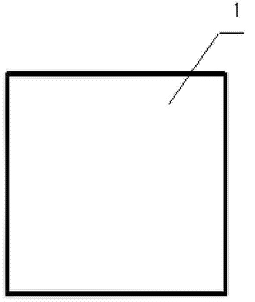
[0028] 1. Reference figure 1 , figure 2 , the iron core punch 1 is blanked into a quadrilateral punch blank, and the size of the punch blank matches the external size of the iron core 4 .

[0029] 2. Clean and deburr the blanks;

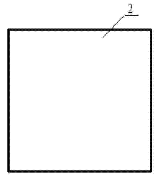
[0030] 3. Reference image 3 , Figure 4 , sizing the punching sheet blanks, laminating and curing to form a quadrilateral iron core blank 2;

[0031] 4. Clean up more than 2 glues of the iron core rough blank;

[0032] 5. Use wire cutting to process the shape of the iron core blank 2, so that it can be processed into a full-circle iron core 4 (see Figure 7 and Figure 8 ).

[0033] refer to Figure 5 , Image 6 , before the wire cutting operation is performed on the iron core blank 2 with a quadrangular shape, the four sides of the iron core blank 2 are symmetrically welded with four process welds 3, so as to facilita...


PUM


Abstract

The invention relates to a manufacturing method of an adhesive type iron core of a motor, comprising the following steps: 1. blanking stamping pieces of the iron core into stamping blank piece and matching the dimension of the stamping piece and the overall dimension of the iron core; 2. carrying out cleaning to the blank piece of the stamping piece and deburring; 3. gluing to the blank piece of the stamping piece, laminating and curing into a rough blank of the iron core; 4. cleaning the residue glue of the rough blank of the iron core; and 5. adopting a line cutting manner to process the shape and the edge of a tooth slot to the rough blank of the iron core. The manufacturing method does not carry out stamping to the stamping piece of the iron core, can simplify the structure of adhesive and laminated mold, reduce the workload of demolding, cleaning and deburring, and can realize low labor intensity, high working efficiency and good product quality.

Description

technical field [0001] The invention relates to a manufacturing method of a motor glued iron core. Background technique [0002] At present, the manufacturing method of the existing motor glued iron core includes the following steps: 1. First, the shape and tooth slot of the iron core punching sheet that constitutes the motor glued iron core are processed and formed (usually, a punching die is used for punching). 2. Cleaning and deburring the formed iron core punching sheet; 3. The iron core punching sheet is glued and laminated in the iron core gluing and lamination die, and then cured into a whole. [0003] However, there are the following problems in the manufacturing method of the existing motor glued iron core: [0004] 1. It is impossible to completely match the shape and the boundary between the sheets of the iron core punching sheet after gluing and lamination, and there is often a phenomenon of dislocation between sheets such as the shape and the teeth, which is no...

Claims


Application Information

Patent Timeline
Patent Type & Authority Patents(China)
IPC IPC(8): H02K15/02
Inventor 王菁雷雄
Owner XIANGTAN ELECTRIC MFG CORP LTD
Why Eureka
Try Eureka