A wheel hub die-casting mold

A die-casting mold and wheel hub technology is applied in the field of wheel hub casting, which can solve the problems of high energy consumption and increase the cost of wheel hub manufacturing, and achieve the effects of reducing the weight of molten aluminum, improving crystallization and density, and improving market competitiveness.

Active Publication Date: 2016-04-06
SIYANG MINGYUXING PRECISION MACHINERY CO LTD
View PDF6 Cites 0 Cited by
  • Summary
  • Abstract
  • Description
  • Claims
  • Application Information

AI Technical Summary

Problems solved by technology

[0003] The technical problem to be solved by the present invention is to provide a wheel hub die-casting mold, which can solve the problem that the four arc-shaped parts of the side mold of the existing wheel hub die-casting mold are respectively driven and pressed by four oil cylinders, and the energy consumption is high, resulting in increased wheel hub manufacturing costs. The problem

Method used


Image

  • A wheel hub die-casting mold
  • A wheel hub die-casting mold
  • A wheel hub die-casting mold

Examples


Embodiment Construction

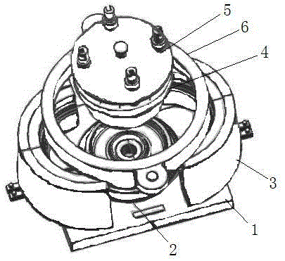
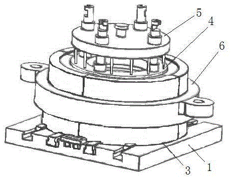
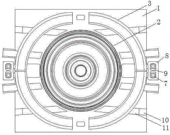
[0020] Such as figure 1 , figure 2 and image 3 A wheel hub die-casting mold is shown, which includes a lower mold 2, a side mold and an upper mold 4 that form a wheel hub casting cavity after being combined. The upper end of the upper mold 4 is connected with a ejector plate 5. Above, the outer wall of the side form is a truncated cone with a large end at one end and a small taper at the other end with a taper of 8°~12°, and the outer wall of the side form is connected with a An annular clamping sleeve 6, the inner diameter of the clamping sleeve 6 is between the outer diameter of the large end and the outer diameter of the small end of the outer wall of the side mold, and the inner wall is provided with the same taper as the outer wall of the side mold.

[0021] The side mold is composed of four arc sections 3 that are slidably connected to the lower formwork 1, and the four arc sections 3 are divided into two groups respectively located on the left and right sides of the...


PUM


Abstract

The invention discloses a hub die-casting mould. The hub die-casting mould comprises a lower die, a side die and an upper die which are combined to form a hub casting cavity; the lower die is arranged on a lower template, and the side die is formed by glidingly connecting four sections to an arc part of the lower template; four arc parts are respectively located at two groups at left and right sides of the lower die; an included angle at 3-10 degrees is arranged between the gliding traces of two arc parts of every group and diameters in left and right directions of the lower die. The hub die-casting mould further comprises two connecting blocks respectively arranged at outsides of two groups of arc parts, wherein connecting holes are arranged on the connecting blocks, the outer walls of the two arc parts of every group are respectively provided with pulling hooks, and the pulling hooks are glidingly connected to the connecting holes. Through two connecting blocks, two section arc parts of one group are respectively pulled; two connecting blocks are not required to drive by two oil cylinders, thus the oil cylinder energy consumption in the pouring process is reduced by a half, and the manufacturing cost of the hub is greatly reduced; the cavity pressure is provided through a lock die sleeve; the hub die-casting mould overcomes the limit of the oil cylinder specification, and further reduces the manufacturing cost of the hub.

Description

technical field [0001] The invention relates to the field of wheel hub casting, in particular to a wheel hub die-casting mold. Background technique [0002] The wheel hub is the part of the vehicle used to connect the tire and the shaft. From the manufacturing process, it can be divided into three types: integral casting type, integral forging type and composite type. Among them, the integral casting type wheel hub occupies the total output of the wheel hub due to its low cost. About 90%. The manufacturing process of the integral cast wheel hub is to pour aluminum water, that is, liquid aluminum alloy, into the cavity of the mold. After the aluminum water solidifies to form a wheel hub blank, it is demoulded and cooled, and then deburred, polished, and surface treated to obtain the finished wheel hub. ;According to the different pouring process of aluminum water, it is divided into gravity casting and pressure casting; the structure of the wheel hub is a cylindrical shape c...

Claims


Application Information

Patent Timeline
Patent Type & Authority Patents(China)
IPC IPC(8): B22D17/22
Inventor 贾敏栓谭兴祥徐国兴
Owner SIYANG MINGYUXING PRECISION MACHINERY CO LTD
Why Eureka
Try Eureka