Vehicle seat
A seat and vehicle technology, applied in vehicle seats, vehicle parts, special positions of vehicles, etc., can solve problems such as inability to absorb loads, and achieve the effect of suppressing diving, saving space, and realizing space.
- Summary
- Abstract
- Description
- Claims
- Application Information
AI Technical Summary
Problems solved by technology
Method used
Image

Examples
no. 1 approach
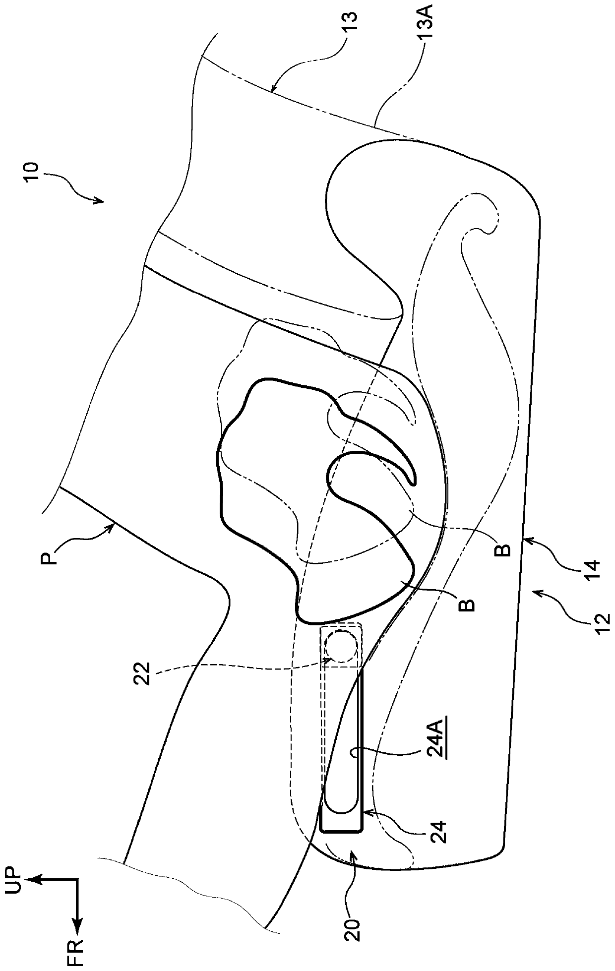
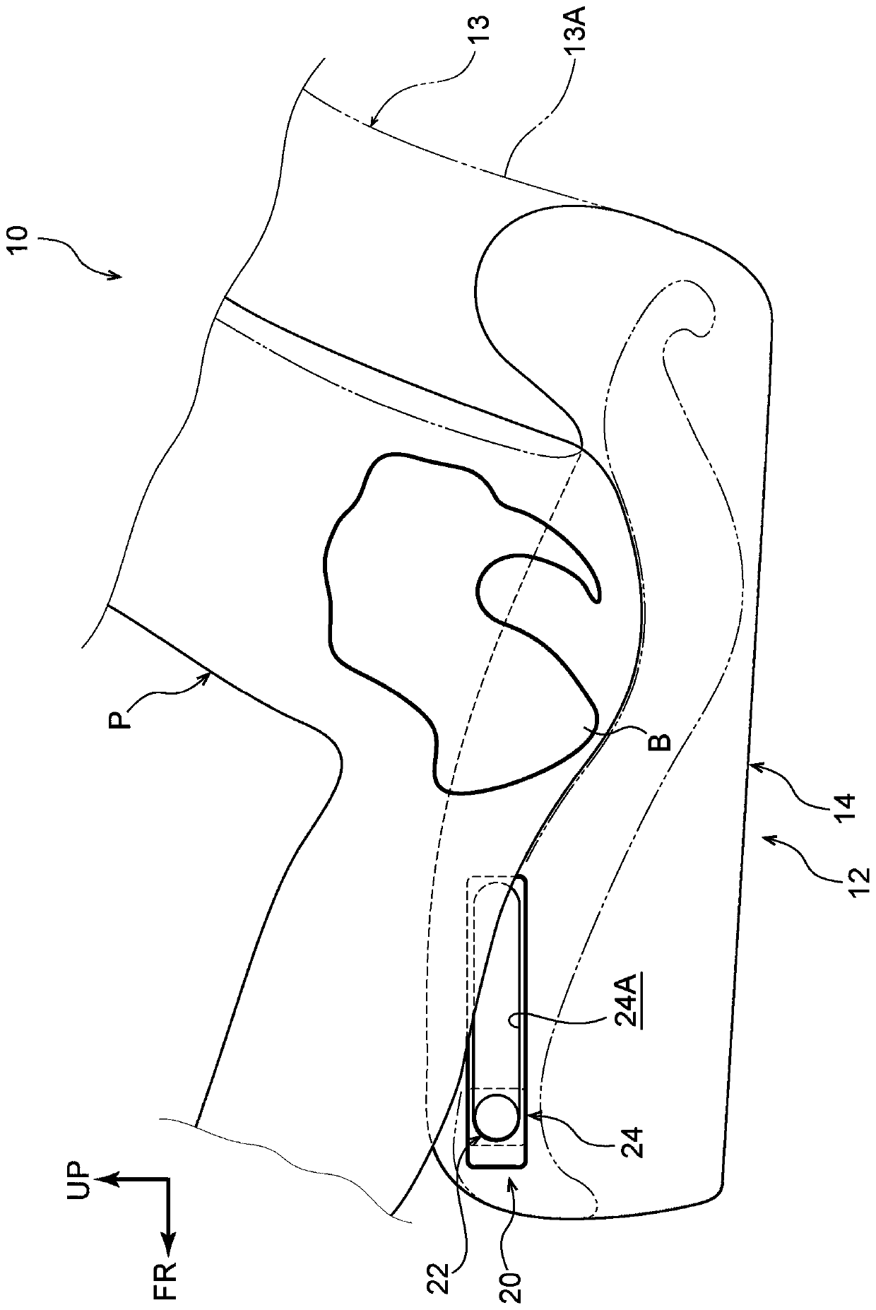
[0057] Below, use Figure 1 to Figure 9 The vehicle seat 10 of the first embodiment will be described. In addition, the arrow FR shown suitably in each figure shows a vehicle front direction, the arrow UP shows a vehicle upward direction, and the arrow RH shows a vehicle right direction. Hereinafter, when the directions of front, rear, left, right, and up and down are used for description, unless otherwise specified, front and rear in the vehicle front and rear direction, left and right in the vehicle left and right direction (vehicle width direction), and up and down in the vehicle up and down direction are meant.
[0058] (The overall structure of the vehicle seat)
[0059] Such as figure 1 As shown, the vehicle seat 10 of the present embodiment includes a seat cushion 12 , and the seat cushion 12 supports the buttocks and thighs of the occupant P seated on the vehicle seat 10 . In addition, the lower end portion 13A of the seat back 13 is connected to the rear end portio...
no. 2 approach
[0110] Next, refer to Figure 10-16 A second embodiment will be described. In addition, about the structure and function which are basically the same as those of 1st Embodiment, the same code|symbol as 1st Embodiment is attached|subjected, and the appropriate description is abbreviate|omitted.
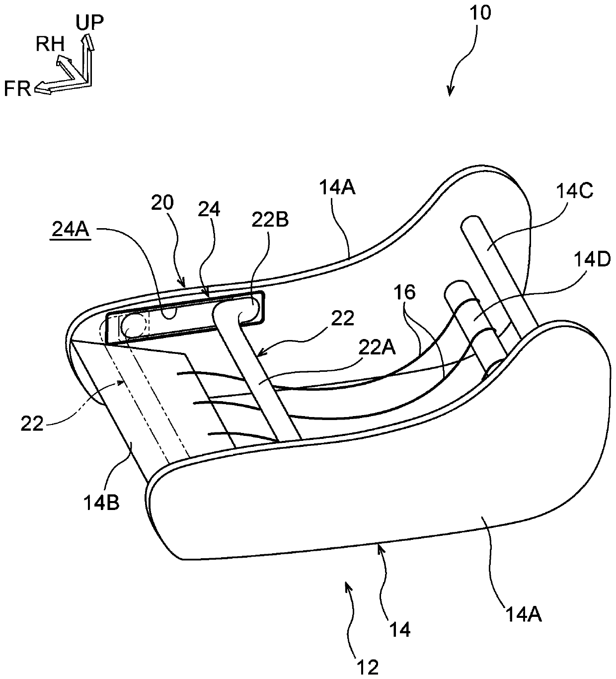
[0111] Such as Figure 10 and Figure 11 As shown, the vehicle seat 50 of the present embodiment includes the seat cushion 12 and the seat back 13 in the same manner as the first embodiment. In addition, the seat cushion 12 is configured to include a seat cushion frame 14 as a skeleton member and a plurality of seat cushion springs 16 attached to the seat cushion frame 14 . In addition, in this embodiment, although the S spring was used as the seat cushion spring 16, it can also be set as the shape similar to 1st Embodiment.
[0112] Here, the front frame 14B of the present embodiment is formed of, for example, a metal plate in an elongated shape, and is arranged with the vehicle w...
no. 3 approach
[0146] Next, refer to Figure 17 , 18 A third embodiment will be described. In addition, about the structure and function which are basically the same as those of 1st Embodiment, the same code|symbol as 1st Embodiment is attached|subjected, and the appropriate description is abbreviate|omitted.
[0147] Such as Figure 17 As shown, the vehicle seat 90 of the present embodiment includes the seat cushion 12 and the seat back 13 similarly to the first embodiment. In addition, the seat cushion 12 is provided with a movement restraining device 91 for restraining the occupant P from moving forward of the seat at the time of a vehicle collision. Hereinafter, details of the movement suppressing device 91 will be described.
[0148] (movement suppression device)
[0149] The movement suppressing device 91 is arranged on the seat front side of the seat cushion 12 and includes a link member 92 attached to the seat cushion frame 14 . The link member 92 includes a long first link 93 ...
PUM
 Abstract
Description
Claims
Application Information
 - R&D Engineer
- R&D Manager
- IP Professional
- Industry Leading Data Capabilities
- Powerful AI technology
- Patent DNA Extraction
Browse by: Latest US Patents, China's latest patents, Technical Efficacy Thesaurus, Application Domain, Technology Topic.
© 2024 PatSnap. All rights reserved.Legal|Privacy policy|Modern Slavery Act Transparency Statement|Sitemap