
Ceiling fan, ceiling fan motor control method and ceiling fan motor control device

A technology for motor control and ceiling fans, applied in pump devices, pump control, control systems, etc., can solve problems such as large technical service and commodity inventory, heavy motor load, ceiling fan execution, etc., to avoid abnormal operation and good heat dissipation. effect of effect

Active Publication Date: 2020-06-19
IND TECH RES INST
View PDF7 Cites 0 Cited by
  • Summary
  • Abstract
  • Description
  • Claims
  • Application Information

AI Technical Summary

Problems solved by technology

However, such an approach will make the control program have to give different set speeds according to the different blades of the ceiling fan, which will lead to great technical service and commodity inventory problems.
[0003] Furthermore, because the ceiling fan motor and driver will produce many different changes according to the cross-matching of the blade size, shape, material, etc., but the set target speed is fixed, so when the user replaces different materials or the size of the blade, it may cause the ceiling fan to fail to perform according to the original setting when rotating
It may even increase the load on the motor after replacing the blades, and the motor will continuously increase the output power in order to control the target speed, eventually causing the output power to exceed the load and overheating

Method used


Image

  • Ceiling fan, ceiling fan motor control method and ceiling fan motor control device
  • Ceiling fan, ceiling fan motor control method and ceiling fan motor control device
  • Ceiling fan, ceiling fan motor control method and ceiling fan motor control device

Examples


Embodiment Construction

[0060] The detailed features and advantages of the present invention are described in detail below in the embodiments, the content of which is sufficient to enable any person familiar with the relevant art to understand the technical content of the present invention and implement it accordingly, and according to the content disclosed in this specification, the scope of claims and the accompanying drawings , anyone skilled in the relevant art can easily understand the related objects and advantages of the present invention. The following examples further illustrate the concept of the present invention in detail, but do not limit the scope of the present invention in any way.

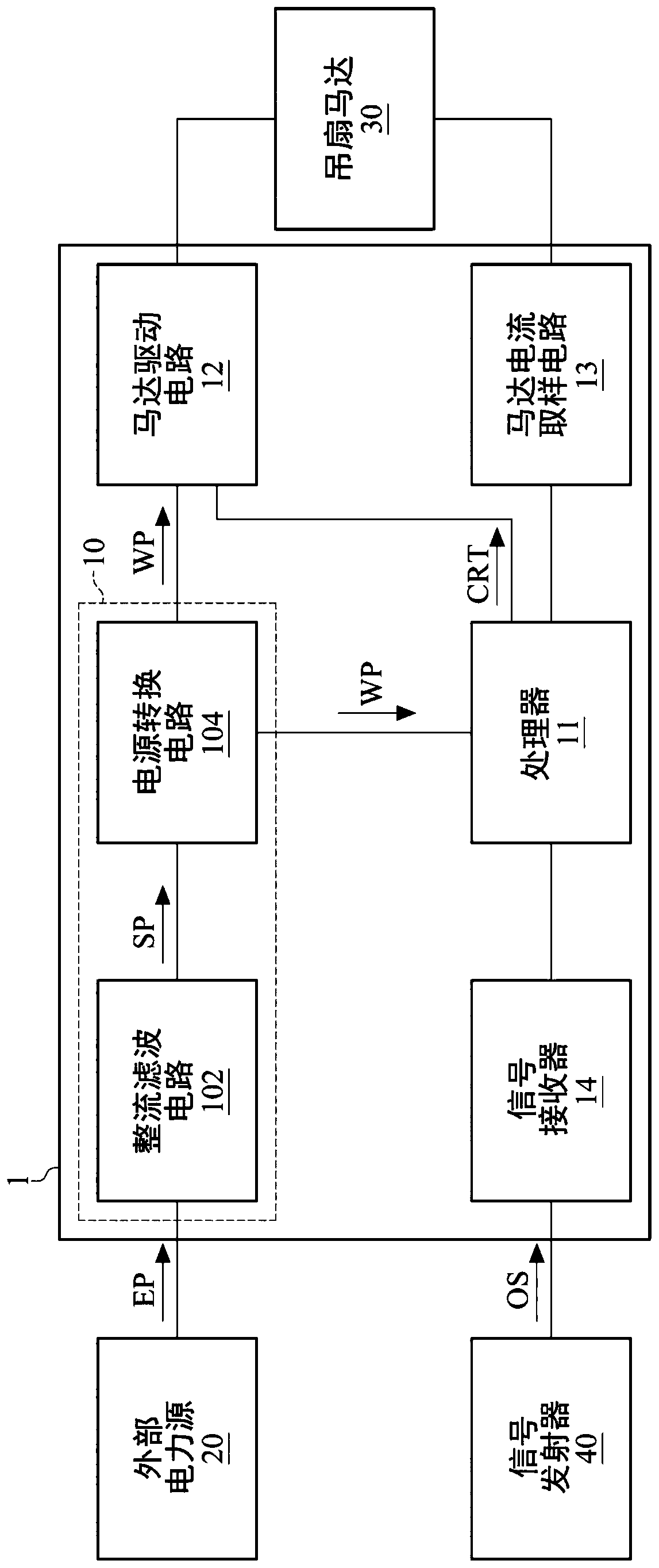
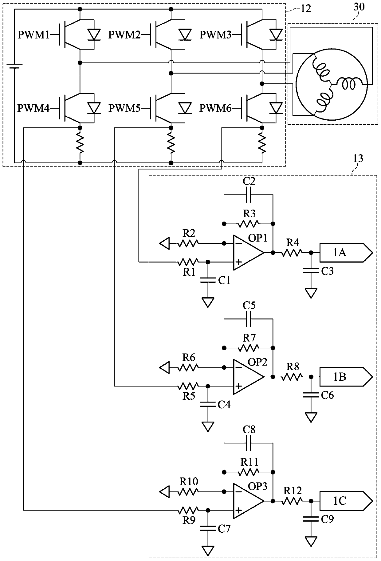
[0061] Please refer to figure 1 , figure 1 A functional block diagram of a ceiling fan motor control device according to an embodiment of the present invention. like figure 1 As shown, the ceiling fan motor control device 1 includes a power supply module 10 , a processor 11 , a motor driving circuit 12...


PUM


Abstract

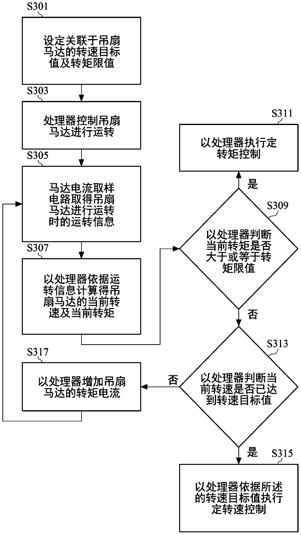
A ceiling fan, a ceiling fan motor control method, and a ceiling fan motor control device. The ceiling fan motor control method includes setting a rotational speed target value and a torque limit value associated with the ceiling fan motor. The processor controls the ceiling fan motor to operate. The operation information of the ceiling fan motor is obtained by the motor current sampling circuit. The current rotational speed and current torque of the ceiling fan motor are calculated by the processor according to the operation information. The processor is used to judge whether the current torque is greater than or equal to the torque limit, and when the current torque is greater than or equal to the torque limit, the constant torque control is executed, and when the current torque is less than the torque limit, it is further judged whether the current speed is The speed target value has been reached. When the processor determines that the current rotational speed reaches the rotational speed target value, the processor executes constant rotational speed control according to the rotational speed target value, and when the processor determines that the current rotational speed does not reach the rotational speed target value, the processor increases the torque current of the ceiling fan motor.

Description

technical field [0001] The invention relates to a ceiling fan, a method for controlling a ceiling fan motor, and a control device for the ceiling fan motor, in particular to a ceiling fan, a control method for the ceiling fan motor, and a control device for the ceiling fan motor. Background technique [0002] At present, the ceiling fan rotation control methods on the market all use the blade speed as the main control parameter, and use the constant speed control system to control the rotation of the blades. The target speed required to be achieved by different stages. However, such an approach will make the control program have to give different set speeds according to the different blades of the ceiling fan, which will cause great problems in technical service and commodity inventory. [0003] Furthermore, because the ceiling fan motor and driver will produce many different changes according to the cross-matching of the blade size, shape, material, etc., but the set targe...

Claims


Application Information

Patent Timeline
Patent Type & Authority Patents(China)
IPC IPC(8): F04D27/00F04D25/08
CPCF04D25/088F04D27/004F05D2270/304H02P6/08H02P6/182Y02B30/70H02P6/06
Inventor 黄亮桥张钰炯刘阳光梁志嘉
Owner IND TECH RES INST
Learn More