Check patentability & draft patents in minutes with Patsnap Eureka AI!

Cast-in-situ bored pile concrete pouring height detection device and use method

A technology of height detection device and bored pile, which is applied in the test of foundation structure, construction, foundation structure engineering, etc., to achieve the effect of improving the construction progress and improving the quality of the pile body

Pending Publication Date: 2019-07-09
TIANJIN PORT ENG INST LTD OF CCCC FIRST HARBOR ENG +2
View PDF0 Cites 0 Cited by
  • Summary
  • Abstract
  • Description
  • Claims
  • Application Information

AI Technical Summary

Problems solved by technology

[0005] Aiming at the existing method of detecting the concrete pouring height of bored piles and a series of problems existing in the construction process of bored piles, a device for detecting the pouring height of bored pile concrete and its application method are proposed

Method used


Image

  • Cast-in-situ bored pile concrete pouring height detection device and use method
  • Cast-in-situ bored pile concrete pouring height detection device and use method
  • Cast-in-situ bored pile concrete pouring height detection device and use method

Examples


Embodiment 1

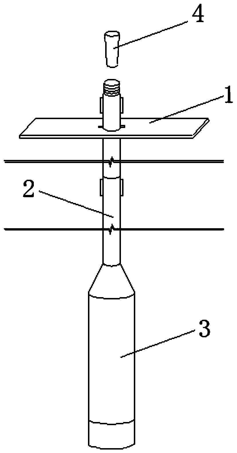
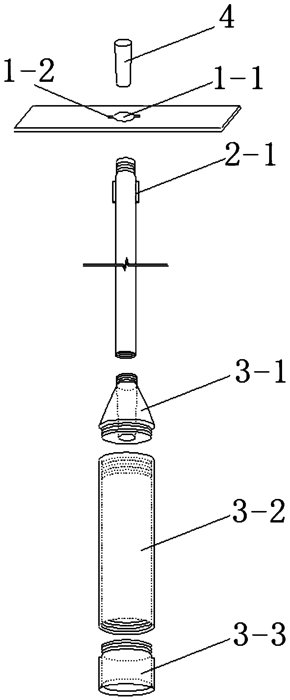
[0041] Such asfigure 1 , 2 As shown, a device for detecting the pouring height of bored pile concrete includes an orifice tray (1), a connecting pipe (2), a coring pipe (3) and a stopper rod (4).

[0042] The center of the orifice tray (1) is provided with an orifice (1-1), and two gaps (1-2) are provided along the diameter of the orifice (1-1); the connecting pipe (2) is a multi-section combined structure, and each The upper end of the connecting pipe is provided with a lug (2-1); the core pipe (3) is composed of a different-diameter pipe collar (3-1), a pipe body (3-2) and a pipe head (3-3) connected in sequence , the reducing pipe collar (3-1) connects the connecting pipe (2) and the pipe body (3-2) into a whole.

[0043] Assemble the different-diameter pipe collar (3-1), pipe body (3-2) and pipe head (3-3) into a core pipe (3); connect the first connecting pipe (2) and the different-diameter pipe collar (3- 1) Carry out threaded connection, and at the same time put the o...

Embodiment 2

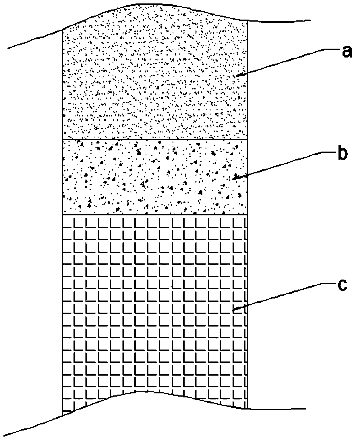
[0061] The difference between this embodiment and Embodiment 1 is that the tube body (3-2) of the core tube can be made of transparent material, such as glass or transparent plastic, so that in step ⑦, it is not necessary to pour out the core tube (3) As long as the outer wall of the pipe body (3-2) is cleaned, the position of the interface between the concrete layer and the mixed layer can be directly observed, and then the pouring height of the cast-in-place concrete can be measured.

Embodiment 3

[0063] Further, the orifice tray (1) is a steel rectangular backing plate, the length of which is usually twice the diameter of the borehole, and its rigidity and thickness are based on the weight that can bear the core pipe (3) and the N-section connecting pipe (2) .


PUM

PropertyMeasurementUnit
Outer diameteraaaaaaaaaa
Thicknessaaaaaaaaaa

Abstract

The invention discloses a cast-in-situ bored pile concrete pouring height detection device and a use method. The device comprises an orifice tray, a connecting pipe, a coring pipe and a plug rod; thecenter of the orifice tray is provided with an orifice, and the diameter of the orifice is provided with two notches; and the connecting pipe is of a multi-section combined structure, a clamping lug is arranged at the upper end of each section of the connecting pipe, and the clamping lugs can penetrate through the orifice and the notches. During use, the orifice tray stretches across a drill hole,connecting pipes are added section by section, the coring pipe is gradually inserted into the deep part of the drill hole until the core taking pipe penetrates through a mixed layer of mud and sediment at the top of the cast-in-place pile, then, the plug rod slides to a reducing pipe hoop along the connecting pipe, and the pipe core of the reducing pipe hoop is blocked, then the connecting pipe is lifted up section by section until the coring pipe is lifted out of the drill hole, then the interface position of a concrete layer and the mixed layer is determined, and the sum of the distance between the interface position and the upper end opening of the reducing pipe hoop and the length of the connecting pipe is the pouring height of cast-in-place pile concrete.

Description

technical field [0001] The invention belongs to the technical field of pile foundation detection, and in particular relates to a device for detecting pouring height of bored pile concrete and a method for using it. Background technique [0002] Bored piles play an important role in ensuring the structural stability of projects and the quality assurance of engineering foundation construction. Concrete pouring height detection is the most effective measure to improve the pouring process of cast-in-place piles and ensure the quality of piles. [0003] The accuracy of concrete pouring height detection not only directly affects the quality of the cast-in-situ pile, but also has a significant impact on the construction progress and cost of the project. In terms of the quality of the pile body, the first batch of concrete is washed out of the conduit and mixed with the mud in the hole to form a laitance dilution layer of a certain thickness. Since the underwater concrete poured wit...

Claims


Application Information

Patent Timeline
IPC IPC(8): E02D33/00
CPCE02D33/00
Inventor 袁方龙杨志军喻志发李立新陈运涛朱耀庭王雪奎陈举李东军
Owner TIANJIN PORT ENG INST LTD OF CCCC FIRST HARBOR ENG
Features
  • R&D
  • Intellectual Property
  • Life Sciences
  • Materials
  • Tech Scout
  • Unparalleled Data Quality
  • Higher Quality Content
  • 60% Fewer Hallucinations
Learn More