
Damage evaluation method and damage evaluation device for magnetic linear object

An evaluation device and evaluation method technology, applied in the direction of the magnitude/direction of the magnetic field, measuring device, magnetic performance measurement, etc., can solve the problems such as the inability to inspect the steel wire rope, and achieve the effect of eliminating the amount of variation and the degree of accurate damage

Active Publication Date: 2019-07-09
TOKYO ROPE MFG
View PDF13 Cites 0 Cited by
  • Summary
  • Abstract
  • Description
  • Claims
  • Application Information

AI Technical Summary

Problems solved by technology

In the damage detector described in Patent Document 1, it is impossible to inspect the wire rope embedded in the concrete while it is embedded in the concrete.

Method used


Image

  • Damage evaluation method and damage evaluation device for magnetic linear object
  • Damage evaluation method and damage evaluation device for magnetic linear object
  • Damage evaluation method and damage evaluation device for magnetic linear object

Examples


Embodiment Construction

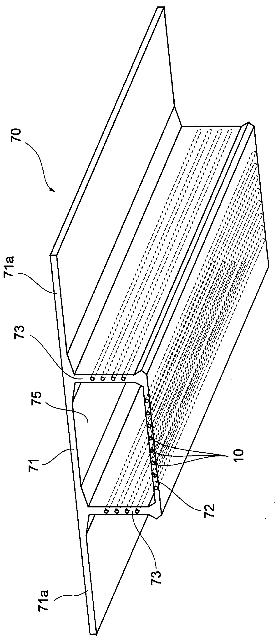
[0026] figure 1 This is a perspective view of the box girders constituting the concrete box girder bridge viewed from below.

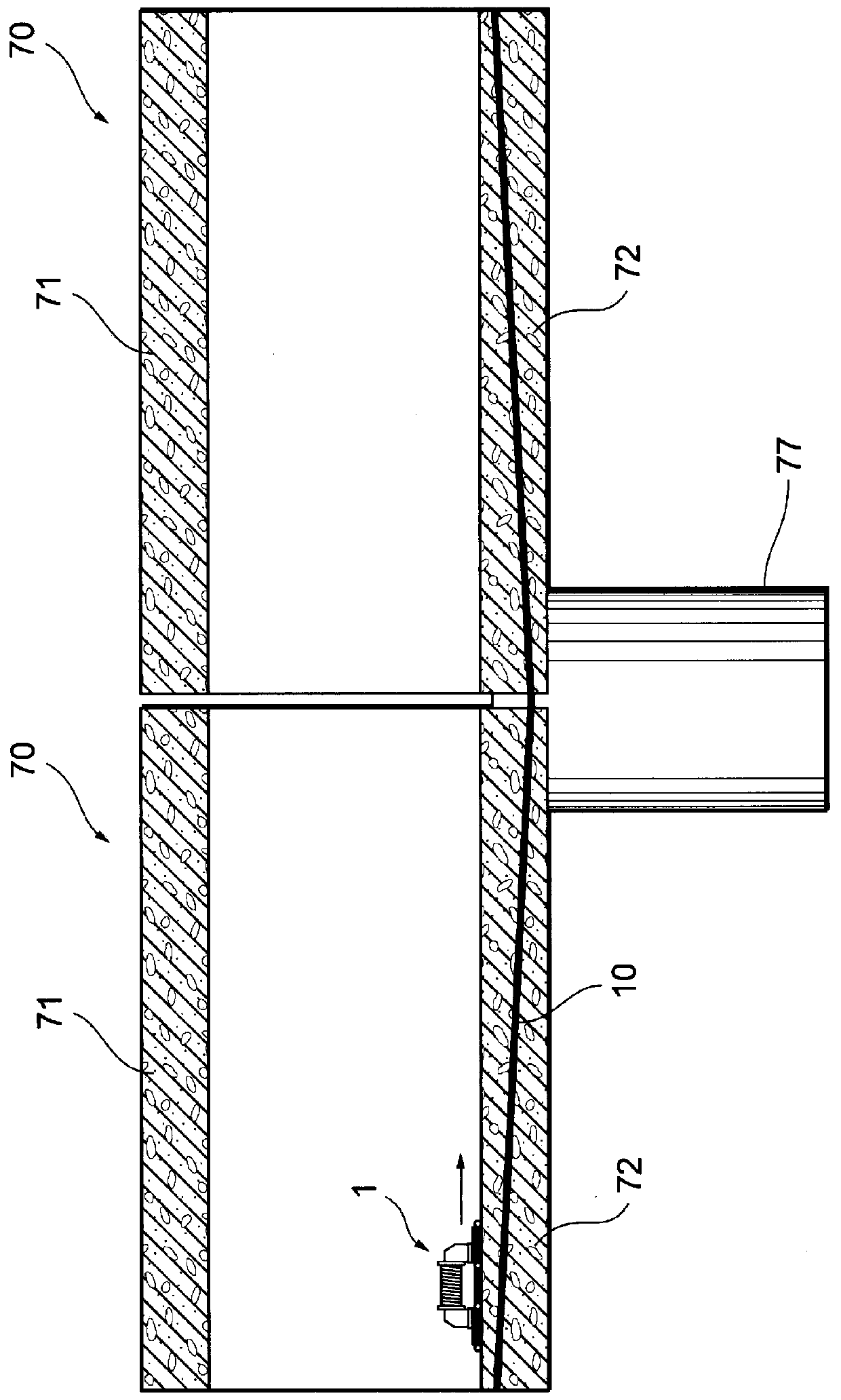
[0027] A concrete box girder bridge is formed by connecting a plurality of concrete box girders along the bridge axis. The box girder 70 is composed of an upper flange 71, a lower flange 72 and a web 73. The lower flange 72 is spaced from the upper flange 71 and arranged substantially parallel to the lower side of the upper flange 71. The webs 73 are connected to the upper flange 71 respectively. The two sides of the flange 71 and the lower flange 72 . The space 75 extending along the bridge axis direction surrounded by the upper flange 71, the lower flange 72 and the webs 73 on both sides is of a size that people can enter, and the concrete box girder bridge (box girder 70) can be constructed from the space 75. examine. Both sides of the upper flange 71 protrude laterally respectively, and the width of the concrete box girder bridge is determined b...


PUM

PropertyMeasurementUnit
diameteraaaaaaaaaa

Abstract

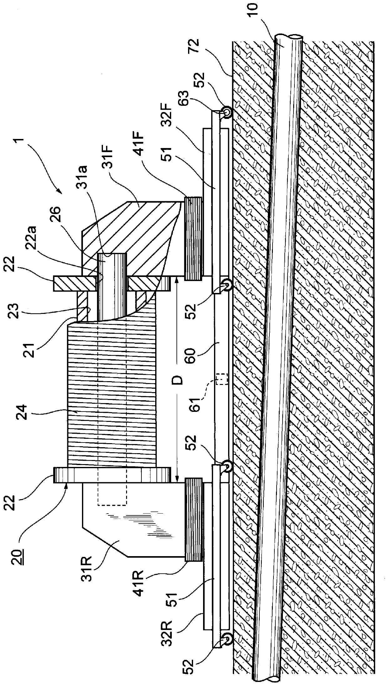
A damage evaluation device (1) is installed and used on a concrete structure in which a tendon (10) to be evaluated for damage is embedded, and includes a magnetizer (20) for generating a magnetic force, and detectors (41F, 41R) for detecting an amount of magnetic variation occurring from a damaged location of the tendon (10) magnetized by the generated magnetic force. The magnetizer includes an excitation coil (24), an iron core (26) inserted in a center hole of the excitation coil, and a pair of columnar yokes (31F, 31R) connected to both ends of the iron core and each extending toward the concrete surface. An electric current is caused to flow through the excitation coil, whereby a magnetic circuit is formed by a yoke shaft, the pair of columnar yokes, and the range of the tendon that is positioned between a pair of plate-shaped yokes. The electric current applied to the excitation coil is controlled so that the magnetic flux density of the tendon is constant.

Description

technical field [0001] The present invention relates to a method and an apparatus for evaluating damage (deterioration state) of a magnetic linear body, typically used for embedding in concrete. Linear bodies include cables, ropes, strands, cords, wires, rods, poles, shafts, and others The linear body in a form extending continuously in one direction includes not only a twisted linear body but also a bundled linear body and a single linear body. In addition, the size of the diameter and the cross-sectional shape are not limited at all. The so-called magnetic linear body refers to a magnetic material, typically a linear body made of a ferromagnetic material. Background technique [0002] Patent Document 1 discloses a wire rope damage detector to which a probe coil is attached by winding the wire rope. [0003] prior art literature [0004] patent documents [0005] Patent Document 1: Japanese Unexamined Patent Publication No. 2002-5896 [0006] The steel wire rope inspe...

Claims


Application Information

Patent Timeline
Patent Type & Authority Applications(China)
IPC IPC(8): G01N27/82
CPCG01N27/82G01N33/383G01R33/072G01R33/0094G01V3/081G01R33/02G01N27/80G01N27/83G01N27/902G01R33/12G01V3/104G01D5/145G01D11/245G01D3/022G01D5/202G01R33/09G01R33/093G01R31/2829G01R33/06
Inventor 糸井宏明金丸博纪桥目佑太
Owner TOKYO ROPE MFG
Learn More