Air compressor performance detection system and detection method
A detection system and detection method technology, applied in the direction of pump testing, mechanical equipment, machines/engines, etc., can solve problems such as prone to safety accidents, consumption, and affecting the use of air compressors
- Summary
- Abstract
- Description
- Claims
- Application Information
AI Technical Summary
Problems solved by technology
Method used
Image

Examples
Embodiment 1
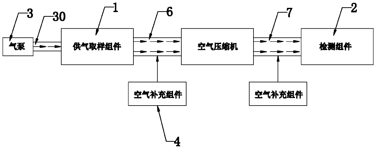
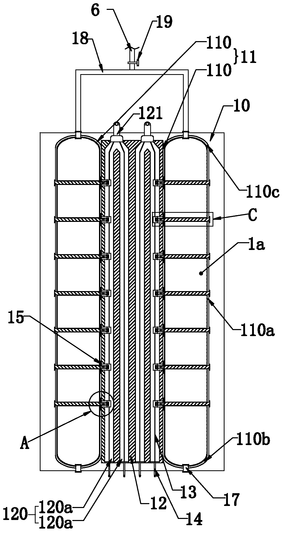
[0031] Such as Figure 1 to Figure 7As shown, the present invention discloses an air compressor performance detection system, which includes an air compressor. In a specific embodiment of the present invention, it includes a detection platform for placing the air compressor, and a Air supply sampling assembly 1 for air, detection assembly 2 for absorbing air from the exhaust end of the air compressor, and air pump 3 for infusing air into the air supply sampling assembly; the air supply sampling assembly 1 and detection assembly 2 pass through the first The air supply pipe 11 and the second air supply pipe 12 are respectively connected to the intake end and the exhaust end of the air compressor, and the first air supply pipe 11 and the second air supply pipe 12 are provided with an air supplementary assembly 4; when the air compressor works , extract the gas in the gas supply sampling assembly 1, and pour this part of the gas into the detection assembly 2, the first gas supply ...
Embodiment 2
[0049] An air compressor performance detection method is characterized in that, comprising the steps of:
[0050] S1 pretreatment: place the air compressor to be tested on the testing platform, and supply power to the circuits inside the U-shaped wire chamber and the spiral wire chamber, and separate the sampling air bag body, the first air supply pipe, the second The air in the second air supply pipe, the air compressor, the second air supply pipe and each detection air bag is vacuumized;
[0051] S2 gas sampling: close the valve on the first gas supply pipe, and supply gas to the inside of each sampling gas bag through the air pump, and complete the gas supply when all the test lights are on;
[0052] S3 gas transfer: open the valve on the first gas supply pipe, and drive the air compressor to extract the air inside each sampling air bag, and pour it into the detection tank;
[0053]S4 Filling layer by layer: open the electric valve on the top of the first layer of detectio...
Embodiment 3
[0060] Embodiment 3, the difference with embodiment 2 is
[0061] An air compressor performance detection method is characterized in that, comprising the steps of:
[0062] S1 pretreatment: place the air compressor to be tested on the testing platform, and supply power to the circuits inside the U-shaped wire chamber and the spiral wire chamber, and separate the sampling air bag body, the first air supply pipe, the second The air in the second air supply pipe, the air compressor, the second air supply pipe and each detection air bag is vacuumized;
[0063] S2 gas sampling: close the valve on the first gas supply pipe, and supply gas to the inside of each sampling gas bag through the air pump, and complete the gas supply when all the test lights are on;
[0064] S3 gas transfer: open the valve on the first gas supply pipe, and drive the air compressor to extract the air inside each sampling air bag, and pour it into the detection tank;
[0065] S4 Filling layer by layer: open...
PUM
 Abstract
Description
Claims
Application Information
 - Generate Ideas
- Intellectual Property
- Life Sciences
- Materials
- Tech Scout
- Unparalleled Data Quality
- Higher Quality Content
- 60% Fewer Hallucinations
Browse by: Latest US Patents, China's latest patents, Technical Efficacy Thesaurus, Application Domain, Technology Topic, Popular Technical Reports.
© 2025 PatSnap. All rights reserved.Legal|Privacy policy|Modern Slavery Act Transparency Statement|Sitemap|About US| Contact US: help@patsnap.com