
Defrosting apparatus and methods for operation thereof

A capacitor, variable technology, applied in the field of defrosting equipment and its operation, capable of solving the problems of late stop, inefficient defrosting of food loads, premature stop of defrosting operation, etc.

Pending Publication Date: 2019-07-19
NXP USA INC
View PDF12 Cites 3 Cited by
  • Summary
  • Abstract
  • Description
  • Claims
  • Application Information

AI Technical Summary

Problems solved by technology

[0003] While good defrosting results can be obtained with such systems, dynamic changes in food load impedance can lead to inefficient defrosting of food loads
In addition, inaccuracies inherent in determining the length of a defrost operation based on weight may cause the defrost operation to be stopped prematurely or late after it has begun to cook the food load

Method used


Image

  • Defrosting apparatus and methods for operation thereof
  • Defrosting apparatus and methods for operation thereof
  • Defrosting apparatus and methods for operation thereof

Examples


Embodiment Construction

[0081] The following detailed description is merely illustrative in nature and is not intended to limit the subject matter or embodiments of the application or the application and uses of such embodiments. As used herein, "exemplary" and "example / example" mean "serving as an example, instance, or illustration." Any implementation described herein as exemplary or example is not necessarily to be construed as preferred or advantageous over other implementations. Furthermore, there is no intention to be bound by any expressed or implied theory presented in the preceding technical field, background or the following detailed description.

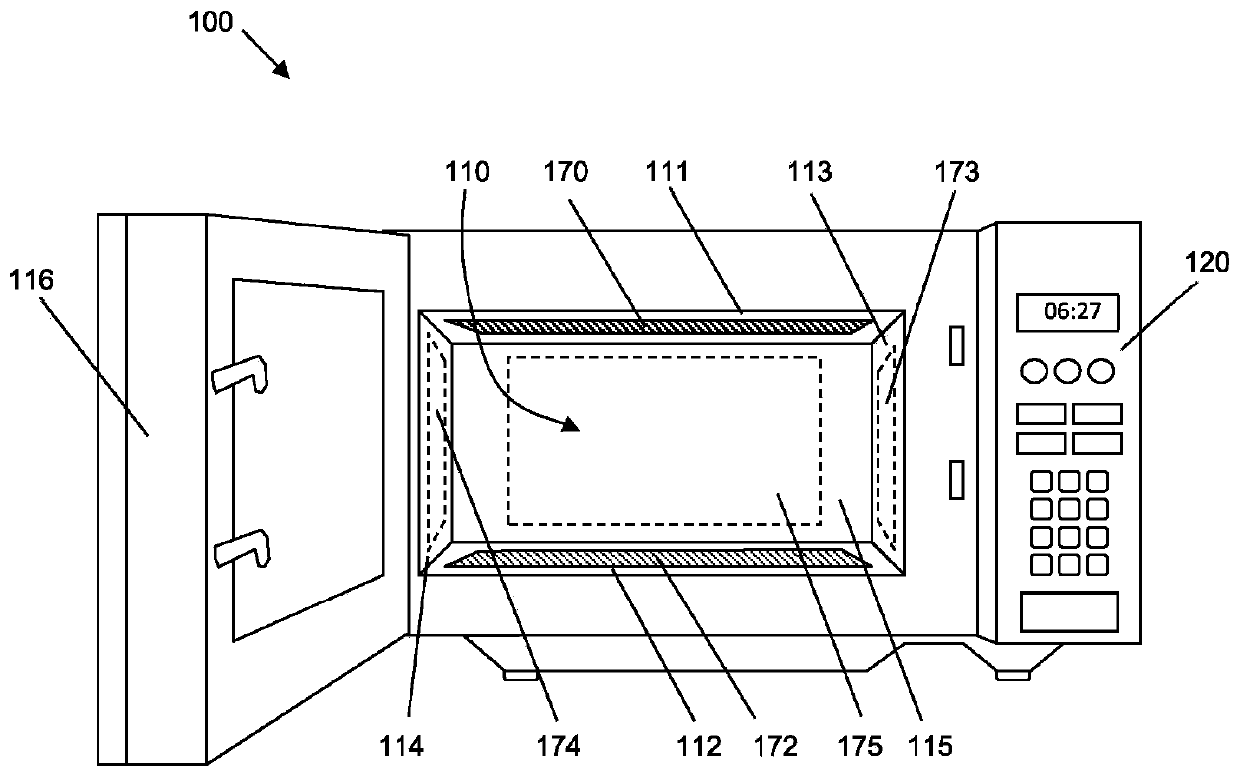
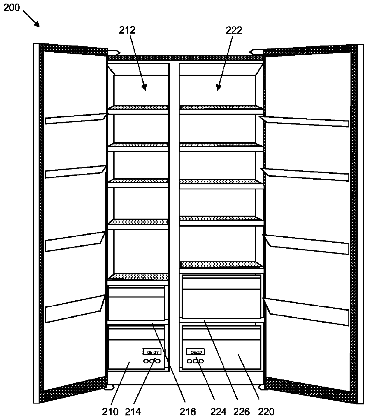
[0082] Embodiments of the subject matter described herein relate to solid state defrost devices that may be incorporated into stand-alone appliances or other systems. As described in more detail below, embodiments of solid state defrost devices include both "unbalanced" defrost devices and "balanced" devices. For example, an exemplary "unbalanc...


PUM


Abstract

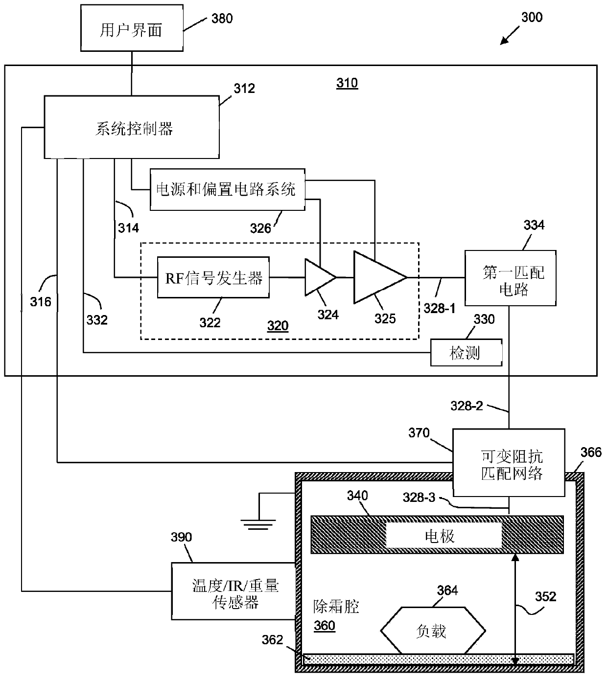
The invention relates to a defrosting apparatus and methods for operation thereof. The system includes an RF source, two electrodes proximate to a cavity within which a load to be defrosted is positioned, a transmission path between the RF signal source and the electrodes, and an impedance matching network electrically coupled along the transmission path between the output of the RF signal sourceand the electrodes. The system also includes power detection circuitry coupled to the transmission path and configured to detect reflected signal power along the transmission path. A system controlleris configured to modify, based on the reflected signal power, values of variable capacitors of the impedance matching network to reduce the reflected signal power. The impedance matching network maybe a single-ended network or a double-ended network.

Description

technical field [0001] Embodiments of the subject matter described herein relate generally to apparatus and methods for defrosting loads using radio frequency (RF) energy. Background technique [0002] Traditional capacitive food defrosting (or defrosting) systems include large planar electrodes housed within a heated compartment. After placing the food load between the electrodes and bringing the electrodes into contact with the food load, low power electromagnetic energy is supplied to the electrodes to gently heat the food load. As the food load thaws during defrost, the impedance of the food load changes. Therefore, the power delivered to the food load also changes during defrost. The duration of the defrost operation may be determined, for example, based on the weight of the food load, and a timer may be used to control the stopping of the operation. [0003] While good defrosting results can be obtained with such systems, the dynamic changes in food load impedance c...

Claims


Application Information

Patent Timeline
IPC IPC(8): F25D21/00F25D21/06
CPCF25D21/006F25D21/06H03H7/38H05B6/50H05B6/62H05B6/705F25D23/12H05B6/688H03H11/54H03H11/28
Inventor J·M·马克卡维勒P·M·J·皮埃尔J·E·司各特L·莫金J·西蒙
Owner NXP USA INC
Learn More