Mobile plugging structure

A technology of plug-in structure and movable connection, applied in the direction of connection, contact parts, parts of connection device, etc., can solve the problems of difficult plug-in and loose connection, and achieve the effect of easy plug-in and tight connection

Active Publication Date: 2019-08-02
REPOWER TECH CO LTD
View PDF4 Cites 1 Cited by
  • Summary
  • Abstract
  • Description
  • Claims
  • Application Information

AI Technical Summary

Problems solved by technology

[0003] The purpose of the present invention is to provide a movable plug-in structure to solve the technical problems in the prior art that two plug-in components are difficult to plug in and not tightly connected due to position deviation when they are plugged in by automation equipment

Method used


Image

  • Mobile plugging structure
  • Mobile plugging structure
  • Mobile plugging structure

Examples


Embodiment 1

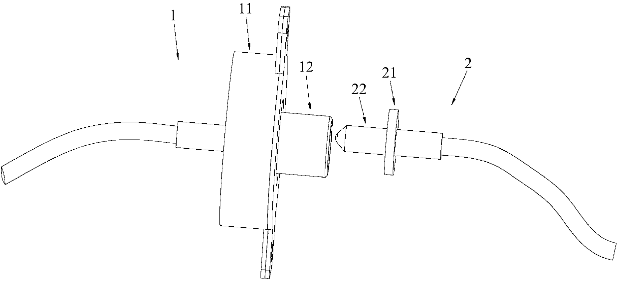
[0029] Please also refer to Figure 1 to Figure 3 , the movable plug structure provided by the present invention will now be described. The movable plug structure includes a first plug assembly 1 and a second plug assembly 2, the first plug assembly 1 includes a first mount 11 and a first plug 12 connected to each other, and the second plug assembly 2 includes interconnected The second mounting base 21 and the second plug 22, the first plug 12 and the second plug 22 are plugged together, in particular, the first plug 12 and the first mounting base 11 and the second plug 22 and the second mounting base 21 are at least One group is movable connection, that is, the movable plug structure of the present invention has the following three situations: the first plug 12 is movably connected with the first mounting base 11, and the second plug 22 is fixedly connected with the second mounting base 21; or, the first The plug 12 is movably connected to the first mounting base 11, and the...

Embodiment approach

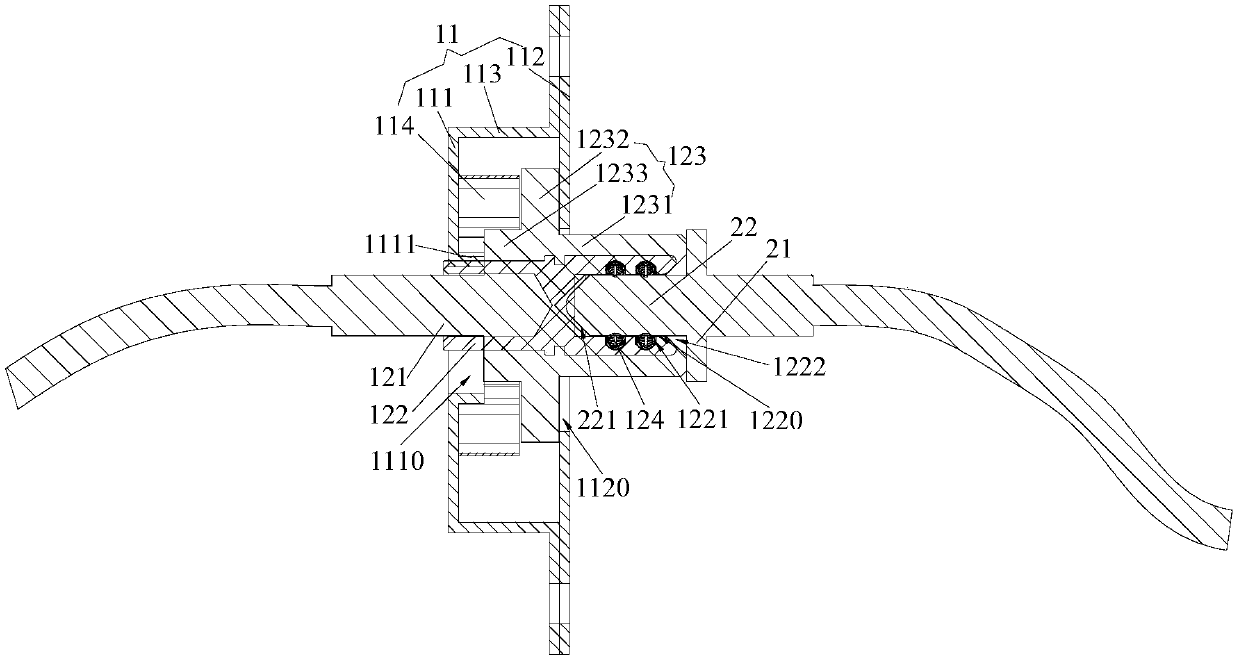
[0037] Further, see figure 2 , as a specific embodiment of the movable plug-in structure provided by the present invention, the above-mentioned first limiting plate 111 is provided with a first limiting hole 1110, and the first limiting hole 1110 runs through the first limiting plate 111 and the first The sleeve 1111 and the second limiting plate 112 are provided with a second limiting hole 1120 . The movable part 123 includes a first cylinder 1231 and a second cylinder 1232, the second cylinder 1232 is connected between the first cylinder 1231 and the second sleeve 1233, and the outer diameter of the first cylinder 1231 is smaller than that of the second cylinder 1232 and the inner diameter of the second limiting hole 1120, the outer diameter of the second cylinder 1232 is greater than the inner diameter of the second limiting hole 1120 and the inner diameter of the first limiting hole 1110, the outer diameter of the cable 121 is smaller than the first The inner diameter of...

Embodiment 2

[0042] The technical characteristics of the active plug structure in this embodiment are basically the same as those in Embodiment 1, the difference is: please refer to Figure 4 and Figure 6 The above-mentioned movable part 123 includes a socket part 1234 and two movable parts 1235, and the above-mentioned first installation seat 11 corresponding to the two movable parts 1235 includes two first limiting plates 111, two second limiting plates 112, two connecting bodies 113 and two Reset part 114, see Figure 5 , the sleeve part 1234 covers the connection between the cable 121 and the connector 122, and the two movable parts 1235 are respectively connected to the opposite sides of the sleeve part 1234, and the movable part 1235 can be moved to stop the second limiting plate 112 and the Between the first limiting plates 111 , the second sleeve 1233 protrudes from the movable portion 1235 . When the movable socket structure of this embodiment is working, the second limiting pl...


PUM


Abstract

The invention provides a mobile plugging structure. The mobile plugging structure includes a first plugging assembly and a second plugging assembly, wherein the first plugging assembly includes a first mounting seat and a first plug which are mutually connected, the second plugging assembly includes a second mounting seat and a second plug which are mutually connected, the first plug and the second plug are for plugging, and at least one group of the first plug and the first mounting seat and the second plug and the second mounting seat is in movable connection. The mobile plugging structure is advantaged in that at least one group of the first plug and the first mounting seat and the second plug and the second mounting seat is set to be in movable connection, when the first plug and the second plug are plugged by an automation device, the first plug and / or the second plug can be moved within a certain range, and thereby the first plug and the second plug can be easily inserted into position without any positional deviation, so the mobile plugging structure is suitable for use in automation equipment.

Description

technical field [0001] The invention belongs to the technical field of plug-in structures, and more specifically relates to a movable plug-in structure. Background technique [0002] At present, in the use and testing process of electronic products, plug-in structures are required for connection. The general plug-in structure includes two plug-in components that are plugged into each other. When the plug-in is performed manually, the position of the plug-in components can be manually adjusted, and the plug-in is easy to succeed. However, when using automation equipment for plugging, because both ends of the plugging are fixedly installed on the automation equipment, and then the automation equipment is used to approach and plug in, and in this process, if there is a position deviation between the plugging components at both ends, It will be difficult to successfully plug in successfully. At the same time, if too much space is reserved for smooth plugging, it will lead to l...

Claims


Application Information

Patent Timeline
Patent Type & Authority Applications(China)
IPC IPC(8): H01R13/627H01R13/629H01R43/26H01R13/10
CPCH01R13/10H01R13/627H01R13/629H01R43/26
Inventor 毛广甫
Owner REPOWER TECH CO LTD
Why Eureka
Try Eureka