

Horizontal high-speed unpacking machine and unpacking method
A technology of unpacking machine and high speed, which is applied in the field of horizontal high-speed unpacking machine and unpacking, which can solve the problems of limiting the efficiency of the production line and not being able to adapt to the speed of the upper and lower production equipment.
- Summary
- Abstract
- Description
- Claims
- Application Information
AI Technical Summary
Problems solved by technology
Method used
Image

Examples
Embodiment Construction
[0036] The present invention will be described in detail below in conjunction with the accompanying drawings and embodiments.
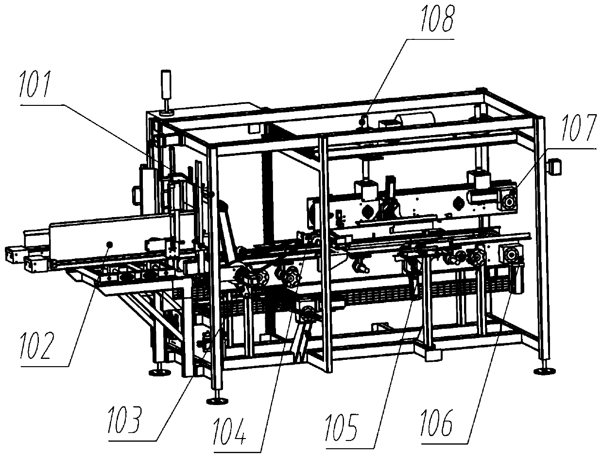
[0037] refer to Figure 1 to Figure 7 As shown, the horizontal high-speed case unpacking machine in one embodiment provided by the present invention includes a frame part 101, and a box blank conveyor 102, a case taking mechanism 103, a case opening mechanism 104, The folding mechanism 105 and the carton conveying device, the input grabbing position of the box taking mechanism 103 is docked with the output end of the box blank conveyor 102, the output code placement of the box taking mechanism 103 is docked with the carton conveying device, the unpacking mechanism 104 and the folding page The mechanism 105 is arranged on both sides of the carton conveying device; the box taking mechanism is used to grab the box blank from the box blank conveyor 102 and place it on the carton conveying device, and the carton conveying device will convey the box blank t...
PUM
 Abstract
Description
Claims
Application Information