
A method of surface element blanking for space target imaging simulation

A technology of space objects and bins, applied in radio wave measurement systems, instruments, etc., can solve problems such as low efficiency and long time, and achieve the effects of reducing the number of times, high-speed bin occlusion judgment, and high-precision fast occlusion judgment

Active Publication Date: 2022-05-20
HARBIN INST OF TECH
View PDF13 Cites 0 Cited by
  • Summary
  • Abstract
  • Description
  • Claims
  • Application Information

AI Technical Summary

Problems solved by technology

[0005] The purpose of the present invention is to solve the problem of long time and low efficiency in the method of judging the occlusion of the facets by using the mutual traversal method of all the facets under the condition of a large number of micro-facets

Method used


Image

  • A method of surface element blanking for space target imaging simulation
  • A method of surface element blanking for space target imaging simulation
  • A method of surface element blanking for space target imaging simulation

Examples


specific Embodiment approach 1

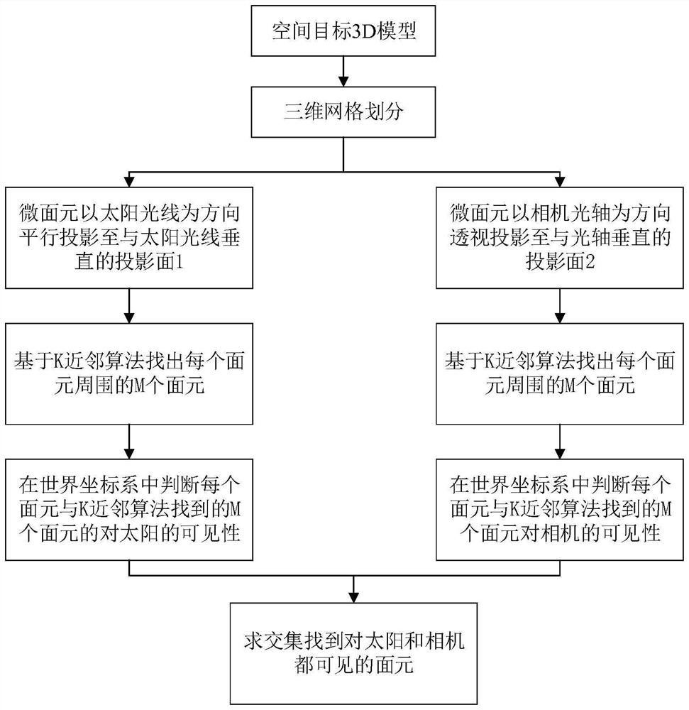
[0021] Specific embodiment one, combining figure 1 This embodiment will be described.

[0022] A method for blanking a space target imaging simulation panel described in this embodiment, the method includes the following steps:

[0023] Step 1: Determine the visibility of the surface element to the sun light source. Assuming that the space target is in the world coordinate system, taking the triangular surface element as an example, the coordinates of the three vertices of the Nth mesh of the space target in the world coordinate system are P N1 (X N1 ,Y N1 ,Z N1 ), P N2 (X N2 ,Y N2 ,Z N2 ) and P N3 (X N3 ,Y N3 ,Z N3 ), the center point coordinate of the surfel is C N (X N ,Y N ,Z N ).

[0024] The direction of the sun's rays in the world coordinate system is S = (X S ,Y S ,Z S ), put P N1 , P N2 , P N3 and C N The projection plane parallel to the vertical optical axis along the direction of the sun's rays is the first projection plane, and the coordinat...

Embodiment

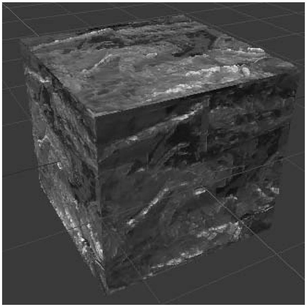
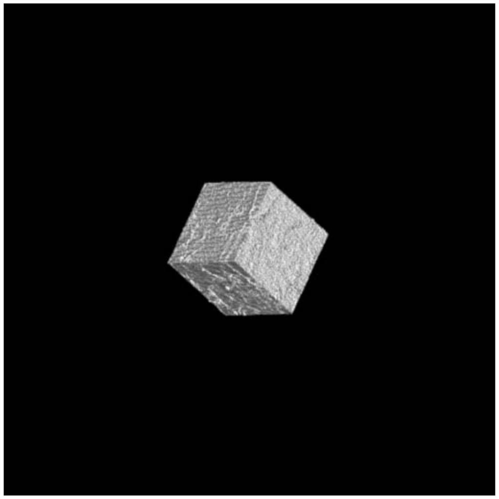
[0043] The simulation experiment is carried out according to the specific implementation. Taking the space target shown in Fig. 2(a) as an example, the surfel division is about 4.89×10 5 If M=40, then the time consumption of the occlusion judgment method based on mutual traversal of all target surfaces is about 80 hours; the time consumption of the method proposed in the present invention is about 5 seconds. Fig. 2(b) is the result of the simulated imaging of Fig. 2(a) using the present invention.


PUM


Abstract

The invention discloses a space target imaging simulation surface element blanking method, relates to a space target imaging simulation surface element blanking method, and belongs to the technical field of target imaging simulation. In order to solve the problem of long time and low efficiency in the method of traversing all the facets to judge the occlusion of the facet under the condition of a large number of micro-facets. A method for blanking surface elements of space object imaging simulation according to the present invention includes a surface element blanking part to the sun light source and a camera blanking part, and the surface element blanking part to the sun light source refers to judging each micro-facet on the surface of the space object Whether the element can receive sunlight, the part of the face element to the camera blanking refers to judging the visibility of each micro-facet element of the space object to the camera. Intersect the surface elements visible to the sun light source and the surface elements visible to the camera to get all the surface elements visible to both the sun light source and the camera. The present invention is suitable for surface element blanking in space object imaging simulation.

Description

technical field [0001] The invention relates to a space target imaging simulation surface element blanking method, and belongs to the technical field of target imaging simulation. Background technique [0002] When simulating space target imaging, the target surface is usually divided into tiny triangular / tetragonal facets to judge the distribution of sunlight energy reflected by each facet on the imaging focal plane, so as to obtain a target simulation image based on radiation transfer. . In this process, it is necessary to judge the visibility of all micro-surface elements to the sun light source and camera, so as to remove the influence of occluded surface elements on imaging. [0003] The general method for judging surfel occlusion is to traverse all the surfels of the target with each other. This method is accurate in calculation, but requires a large amount of computation. Due to the complex structure of the surface of the space target, the surface is rough and undul...

Claims


Application Information

Patent Timeline
Patent Type & Authority Patents(China)
IPC IPC(8): G01S7/48
CPCG01S7/4804
Inventor 汪洪源颜志强王秉文刘祥康文李崇远陈伟胡海泉武少冲王蓝玉曹尧尧
Owner HARBIN INST OF TECH
Learn More