
Clamping mechanism and feeding device

A technology of clamping mechanism and feeding device, which is applied in the direction of sustainable manufacturing/processing, electrochemical generators, electrical components, etc., and can solve problems such as misalignment of pole pieces and unqualified batteries

Pending Publication Date: 2019-08-09
SHENZHEN CHENGJIE INTELLIGENT EQUIP CO LTD
View PDF0 Cites 0 Cited by
  • Summary
  • Abstract
  • Description
  • Claims
  • Application Information

AI Technical Summary

Problems solved by technology

[0002] During the battery production process, the pole piece needs to be wound into a battery cell. However, the pole piece will inevitably slide sideways during the transmission process. When the above situation occurs, it will lead to height misalignment of the pole piece when it is wound up later. In turn, the risk of substandard batteries produced is greatly increased

Method used


Image

  • Clamping mechanism and feeding device
  • Clamping mechanism and feeding device
  • Clamping mechanism and feeding device

Examples


Embodiment Construction

[0035] In order to facilitate the understanding of the present invention, the present invention will be described more fully below with reference to the associated drawings. Preferred embodiments of the invention are shown in the accompanying drawings. However, the present invention can be embodied in many different forms and is not limited to the embodiments described herein. On the contrary, the purpose of providing these embodiments is to make the disclosure of the present invention more thorough and comprehensive.

[0036] It should be noted that when an element is referred to as being “fixed” to another element, it can be directly on the other element or there can also be an intervening element. When an element is referred to as being "connected to" another element, it can be directly connected to the other element or intervening elements may also be present. The terms "inner", "outer", "left", "right" and similar expressions are used herein for the purpose of descripti...


PUM


Abstract

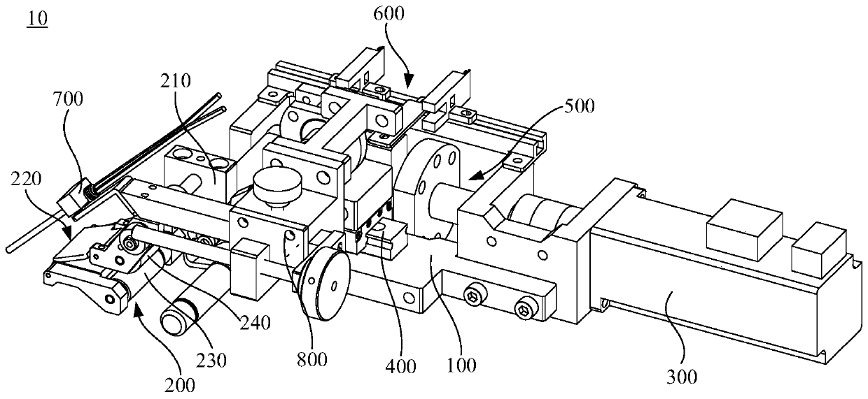
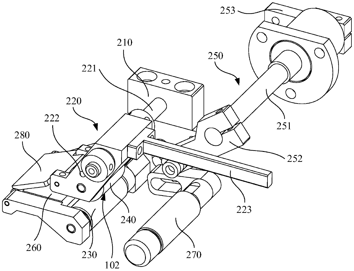
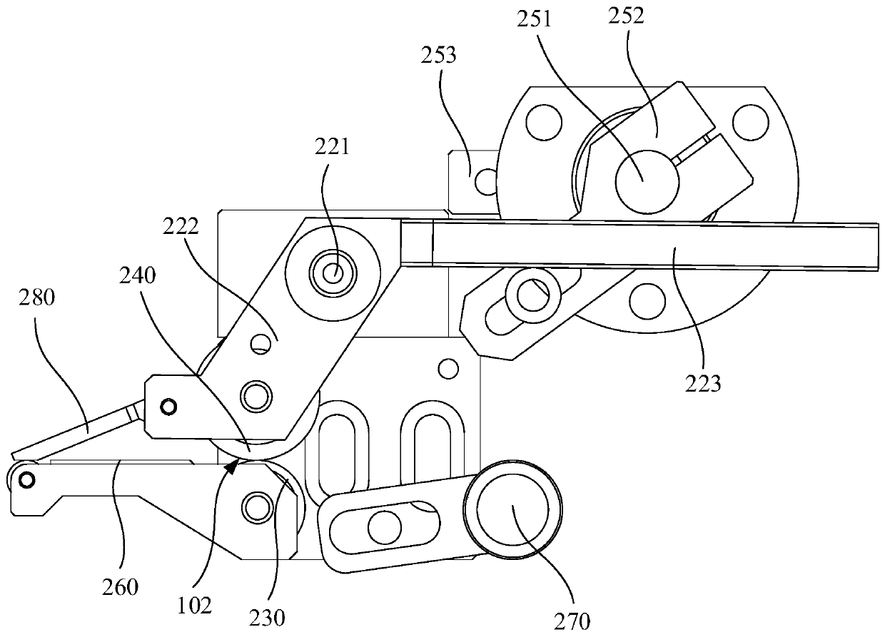
The invention relates to a clamping mechanism and a feeding device. The clamping mechanism is used for fixing and clamping in the pole piece conveying process. The clamping mechanism includes a base,a swing assembly rotatably arranged on the base, a first clamping roller rotatably arranged on the base, a second clamping roller rotatably arranged on the swing assembly, and a driving assembly, wherein a conveying channel for penetration of the pole piece is formed between the first clamping roller and the second clamping roller, the driving assembly presses against the swing assembly, the swingassembly can be driven by the driving assembly to swing relative to the base to drive the second clamping roller to move to approach the first clamping roller, and the pole piece is made to clamp andfix between the first clamping roller and the second clamping roller. The clamping mechanism is advantaged in that the clamping mechanism can prevent lateral slippage of the pole piece during conveying, and thereby a situation in which height misalignment occurs during subsequent winding of the pole piece is prevented, and the product yield of produced battery cells is effectively guaranteed.

Description

technical field [0001] The invention relates to the technical field of battery winding, in particular to a clamping mechanism and a feeding device. Background technique [0002] During the battery production process, the pole piece needs to be wound into a battery cell. However, the pole piece will inevitably slide sideways during the transmission process. When the above situation occurs, it will lead to the height misalignment of the pole piece when it is wound subsequently. In turn, the risk of substandard batteries produced is greatly increased. Contents of the invention [0003] Based on this, it is necessary to provide a clamping mechanism and a feeding device that can enhance the stability of pole piece transmission. [0004] A clamping mechanism for clamping and fixing pole pieces during transmission, including: [0005] base; [0006] A swing component is rotatably arranged on the base; [0007] The first nip roller is rotatably arranged on the base; [0008] ...

Claims


Application Information

Patent Timeline
Patent Type & Authority Applications(China)
IPC IPC(8): H01M10/0587
CPCH01M10/0587Y02E60/10Y02P70/50
Inventor 黄森谭国彪刘云
Owner SHENZHEN CHENGJIE INTELLIGENT EQUIP CO LTD
Learn More