
Gas-liquid separation device for self-priming pump

A gas-liquid separation device and a technology for gas-liquid separation, which are applied to the components, pumps, driving pumps, etc. Self-priming pump work efficiency and other issues, to achieve the effect of improving installation conditions

Inactive Publication Date: 2019-08-23
彭定泽
View PDF0 Cites 2 Cited by
  • Summary
  • Abstract
  • Description
  • Claims
  • Application Information

AI Technical Summary

Problems solved by technology

[0002] Existing self-priming pumps generally have two water outlets, namely the vertical water outlet and the parallel water outlet. Usually, in order to prevent the liquid in the impeller chamber from being thrown directly from the parallel water outlet by the impeller during use, the parallel water outlet needs to be closed. , only use the vertical water outlet, when the gas in the pump body is discharged and the liquid fills the pump body, only the vertical water outlet will seriously affect the working efficiency of the self-priming pump. At the same time, the closure of the parallel water outlet will not only reduce the self-priming pump work efficiency, and also reduces the installation conditions of the self-priming pump

Method used


Image

  • Gas-liquid separation device for self-priming pump

Examples


Embodiment Construction

[0013] The present invention will be further described below in conjunction with the accompanying drawings and specific embodiments.

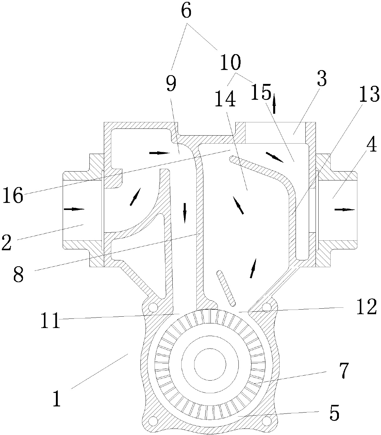
[0014] Such as figure 1 A gas-liquid separation device of a self-priming pump is shown, which has a pump body 1, and the pump body 1 is provided with a pump water inlet 2, a vertical water outlet 3 and a parallel water outlet 4, and the pump body 1 is provided with an impeller chamber 5 and an inner Cavity 6, the impeller chamber 5 is provided with an impeller 7, the inner chamber 6 is divided into a water inlet channel 9 and an outlet channel 10 by a partition plate 8, one end of the water inlet channel 9 is connected to the pump water inlet 2, and the other end is connected to the impeller chamber water inlet 11 One end of the water outlet channel 10 is connected to the impeller chamber water outlet 12, and the other end is connected to the vertical water outlet 3 and the parallel water outlet 4, and the bottom of the parallel water outlet 4 ...


PUM


Abstract

The invention discloses a gas-liquid separation device for a self-priming pump. The gas-liquid separation device is provided with a pump body, wherein a pump water inlet, a vertical water outlet and aparallel water outlet are formed in the pump body; an impeller chamber and an inner cavity are formed in the pump body; an impeller is arranged in the impeller chamber; and the inner cavity is divided into a water inlet channel and a water outlet channel through a partitioning plate. The gas-liquid separation device is characterized in that one end of the water inlet channel is connected with thepump water inlet while the other end of the water inlet channel is connected with an impeller chamber water inlet; one end of the water outlet channel is connected with an impeller chamber water outlet while the other end of the water outlet channel is connected with the vertical water outlet and the parallel water outlet; a gas-liquid separation partitioning plate is arranged at the bottom of the parallel water outlet formed in the water outlet channel, extends toward the vertical water outlet along the bottom of the parallel water outlet, and divides the water outlet channel into two parts,communicating with each other, of the top; and due to arrangement of the gas-liquid separation partitioning plate, liquid which is splashed out of the impeller chamber water outlet can naturally fallback into the impeller chamber because of the gravity once being blocked by the gas-liquid separation partitioning plate under the situation of no closing the parallel water outlet, so that a self-priming function can be quickly and completely achieved, and a mounting situation of the self-priming pump is improved.

Description

technical field [0001] The invention relates to the technical field of water pumps, in particular to a gas-liquid separation device for a self-priming pump. Background technique [0002] Existing self-priming pumps generally have two water outlets, namely the vertical water outlet and the parallel water outlet. Usually, in order to prevent the liquid in the impeller chamber from being thrown directly from the parallel water outlet by the impeller during use, the parallel water outlet needs to be closed. , only use the vertical water outlet, when the gas in the pump body is discharged and the liquid fills the pump body, only the vertical water outlet will seriously affect the working efficiency of the self-priming pump. At the same time, the closure of the parallel water outlet will not only reduce the self-priming pump The working efficiency also reduces the installation conditions of the self-priming pump. Contents of the invention [0003] The invention provides a gas-l...

Claims


Application Information

Patent Timeline
Patent Type & Authority Applications(China)
IPC IPC(8): F04D9/02F04D29/00
CPCF04D9/02F04D29/007
Inventor 彭定泽
Owner 彭定泽
Learn More