
Method and system for fault diagnosis of industrial control equipment

A fault diagnosis system and fault diagnosis technology, applied in the general control system, control/adjustment system, test/monitoring control system, etc., can solve the problems of low efficiency, time-consuming and cumbersome operation of fault diagnosis, and save time and labor costs , Improving the efficiency of diagnosis and reducing the scope of diagnosis

Active Publication Date: 2021-02-19
陆伟庆 +2
View PDF5 Cites 0 Cited by
  • Summary
  • Abstract
  • Description
  • Claims
  • Application Information

AI Technical Summary

Problems solved by technology

In the prior art, when the industrial control system fails, it is necessary to notify the maintenance personnel to go to the site to check the node modules one by one to estimate the cause of the failure. The existing fault diagnosis method is time-consuming, laborious, cumbersome to operate, and the fault diagnosis efficiency is low, resulting in Great waste of manpower and material resources

Method used


Image

  • Method and system for fault diagnosis of industrial control equipment
  • Method and system for fault diagnosis of industrial control equipment
  • Method and system for fault diagnosis of industrial control equipment

Examples


Embodiment Construction

[0042]In order to make the objectives, technical solutions and advantages of the present invention clearer, the technical solutions of the present invention will be described in detail below. Obviously, the described embodiments are only a part of the embodiments of the present invention, rather than all the embodiments. Based on the embodiments of the present invention, all other implementations obtained by a person of ordinary skill in the art without creative work shall fall within the protection scope of the present invention.

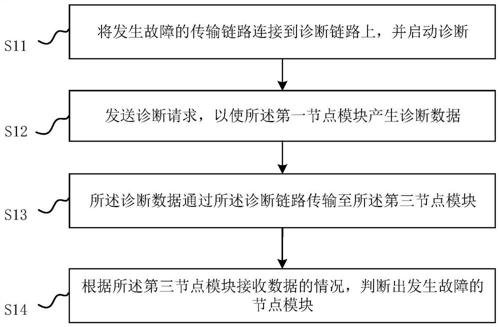
[0043]figure 1 It is a schematic flow chart provided by Embodiment 1 of the method for diagnosing faults of industrial control equipment of the present invention.

[0044]Such asfigure 1 As shown, the fault diagnosis method described in this embodiment includes:

[0045]S11: Connect the failed transmission link to the diagnosis link and start the diagnosis;

[0046]Wherein, one end of the diagnostic link is connected to the first node module, and the other end is co...


PUM


Abstract

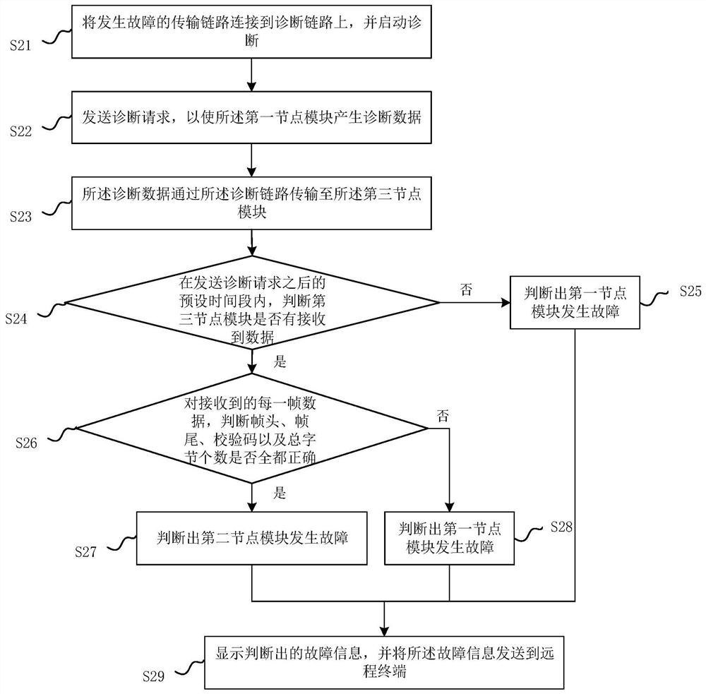
The present invention relates to a method and system for fault diagnosis of industrial control equipment. The diagnosis method includes: connecting the faulty transmission link to the diagnosis link, and starting the diagnosis; sending a diagnosis request to make the first node module generate diagnosis data The diagnostic data is transmitted to the third node module through the diagnostic link; according to the situation of the third node module receiving data, it is judged that the faulty node module occurs; wherein, one end of the diagnostic link is connected to the first node module , the other end is connected to the third node module; the original function of the faulty transmission link is to transmit the data of the first node module to the third node module through the second node module. The method of the present invention can narrow the scope of fault diagnosis, quickly determine the faulty node module, and improve the diagnostic efficiency; in addition, the method does not require maintenance personnel to go to the site to check one by one, and the fault information diagnosed can be sent to the remote terminal, Save time and labor costs.

Description

Technical field[0001]The invention relates to the technical field of industrial control, in particular to a fault diagnosis method and system for industrial control equipment.Background technique[0002]Industrial control equipment is used in more and more industries. Industrial control equipment with different functions is used to achieve specific functions in the industrial field. For example, a water conservancy system with remote monitoring function includes at least: a flow meter, a data conversion processing module and a server set in the water supply pipeline. Under normal circumstances, the flow meter collects the flow information in the pipeline and follows the agreed data transmission protocol The flow information data is transmitted to the data conversion processing module, and then the data conversion processing module performs data processing, and finally transmits the data containing the flow information to the server.[0003]In the above industrial control system, two adj...

Claims


Application Information

Patent Timeline
Patent Type & Authority Patents(China)
IPC IPC(8): G05B23/02
CPCG05B23/0262G05B2219/24065
Inventor 陆伟庆
Owner 陆伟庆
Learn More