
Wireless charging device

A wireless charging and to-be-charged technology, applied in circuit devices, battery circuit devices, current collectors, etc., can solve the problems of low applicability and the use of wireless chargers as a single electronic product, and achieve the effect of improving product applicability

Pending Publication Date: 2019-08-23
吴忠隐
View PDF3 Cites 0 Cited by
  • Summary
  • Abstract
  • Description
  • Claims
  • Application Information

AI Technical Summary

Problems solved by technology

It solves the problem that the existing wireless charger can only be used for a single electronic product and has low applicability

Method used


Image

  • Wireless charging device

Examples


Embodiment Construction

[0035] In order to make the purpose, technical solution and advantages of the present invention clearer, the technical solution of the present invention will be described in detail below. Apparently, the described embodiments are only some of the embodiments of the present invention, but not all of them. Based on the embodiments of the present invention, all other implementations obtained by persons of ordinary skill in the art without making creative efforts fall within the protection scope of the present invention.

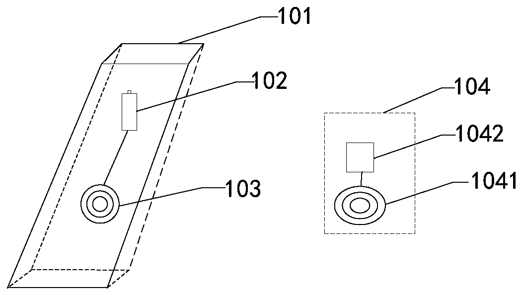
[0036] figure 1 It is a structural diagram of a wireless charging device provided by an embodiment of the present invention. see figure 1 , a wireless charging device, comprising:

[0037] The charging base 101, the power supply structure 102, the power supply coil 103 and the receiver 104; the receiver 104 includes: the power receiving coil 1041 and the voltage adjustment module 1042; wherein the receiver can be set inside the terminal to be charged; it can ...


PUM


Abstract

The invention relates to a wireless charging device comprising: a charging base, a power supply structure, a power supply coil and a receiver, wherein the receiver comprises a power receiving coil anda voltage adjusting module; the power supply structure and the power supply coil are both disposed in the charging base; the receiver is arranged at a set distance of the charging base; the power supply structure is connected to the power supply coil and is used for supplying AC power to the power supply coil; the power supply coil is used for generating a magnetic field under the effect of the AC power; the power receiving coil is connected with the voltage adjusting module and is used for generating induced electromotive force under the effect of the magnetic field, generating the AC powerand supplying the AC power to the voltage adjusting module; a current adjusting module is connected to the battery of a terminal to be charged and is used for converting the received AC power to obtain the adjusted DC power that meets a set condition and further to charge the terminal to be charged; and the set condition is that the current of the DC power is adjusted to meet the current standardrequired by the terminal to be charged. The charging device can realize a shared wireless charging function.

Description

technical field [0001] The invention relates to the technical field of wireless charging, in particular to a wireless charging device. Background technique [0002] With the development of science and technology and the improvement of people's living standards, more and more electronic products have entered people's lives and work. As we all know, electronic products require electric energy during use, and electronic products can only be used normally when they are powered on. [0003] In the prior art, most electronic products need to obtain the power required for their work through batteries. The battery needs to be charged within a certain period of time. However, most of the existing charging methods are charged through a wired power adapter, and this charging method is limited in the movement of the electronic product during the charging process due to the cable. On this basis, wireless chargers appear, and the existing wireless chargers charge electronic products on...

Claims


Application Information

Patent Timeline
IPC IPC(8): H02J7/02H02J50/12H02J5/00
CPCH02J7/025H02J5/005H02J7/027H02J50/12
Inventor 吴忠隐刘双庆
Owner 吴忠隐
Learn More