Supercharge Your Innovation With Domain-Expert AI Agents!

Self-weight lifting tool vehicle

A tooling vehicle and vehicle body technology, which is applied in the direction of parallel load-carrying vehicles, motor vehicles, vehicle parts, etc., can solve the problems of low loading efficiency, improve efficiency, solve waste of bending actions, and eliminate jamming or tilting Effect

Pending Publication Date: 2019-08-27
GREE ELECTRICHEFEI +1
View PDF0 Cites 0 Cited by
  • Summary
  • Abstract
  • Description
  • Claims
  • Application Information

AI Technical Summary

Problems solved by technology

[0004] In order to solve the defect of low loading efficiency in the existing tooling trucks, the invention proposes a self-weight lifting tooling truck

Method used


Image

  • Self-weight lifting tool vehicle
  • Self-weight lifting tool vehicle
  • Self-weight lifting tool vehicle

Examples


Embodiment Construction

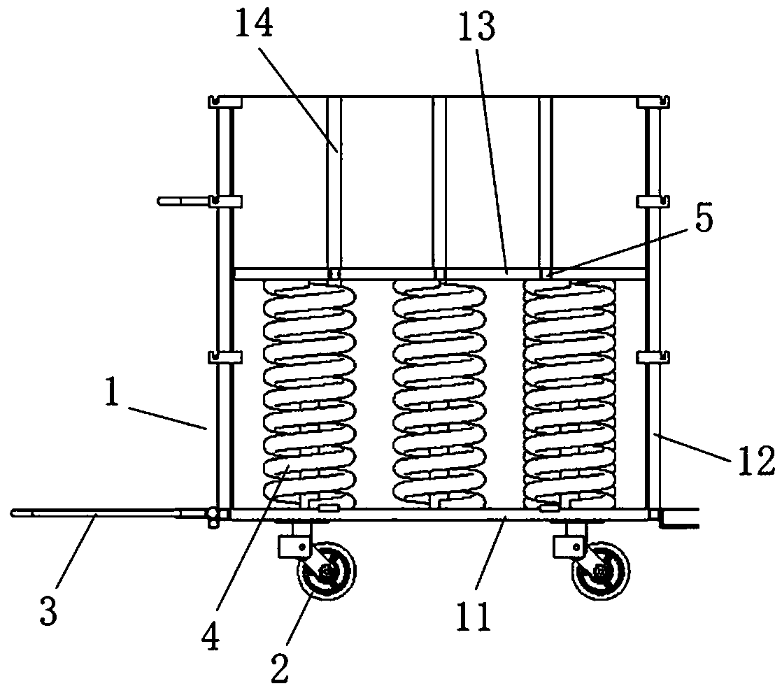
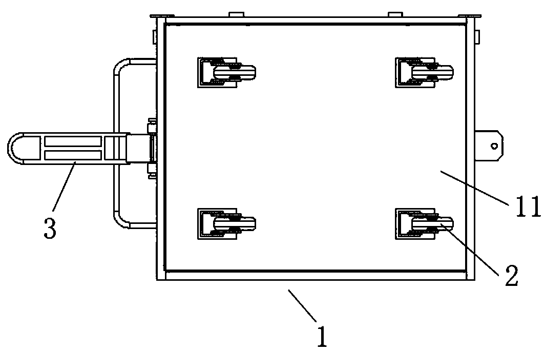
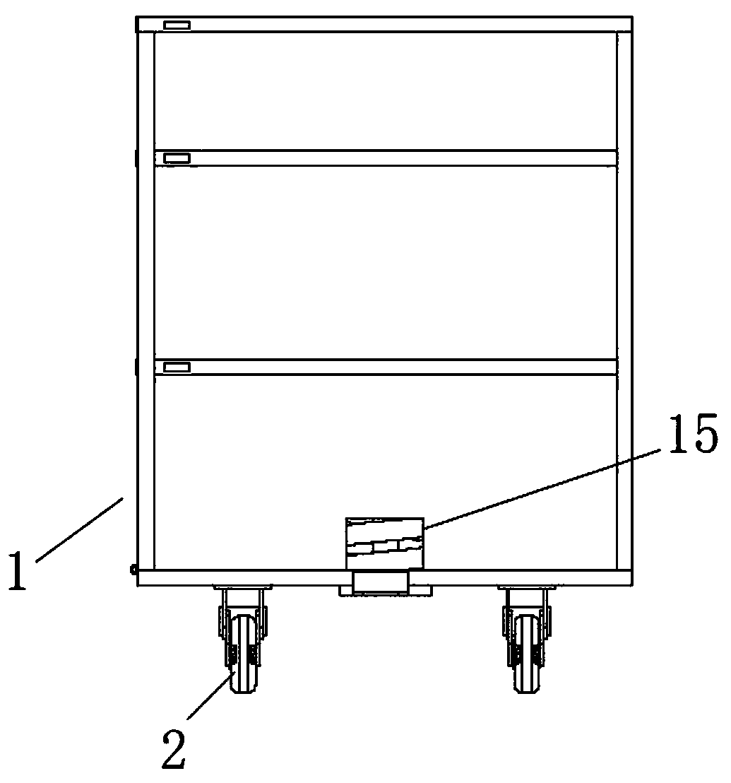
[0024] Such as figure 1 , 2 As shown, the utility vehicle that the present invention proposes self-weight lifting comprises car body 1, and car body 1 is made of fixed base plate 11 and surrounds and is fixed on the side plate 12 on fixed base plate 11, and the opening of car body 1 faces upwards, and the opening of car body 1 A plurality of wheels 2 are installed on the bottom surface, and a traction handle 3 is installed on one side of the fixed base plate 11 . The inner cavity of the car body 1 is provided with a movable floor 13 above the fixed floor 11 , at least one spring 4 is arranged between the fixed floor 11 and the movable floor 13 , and the spring 4 supports the movable floor 13 . When the employee continuously places materials on the movable floor 13, the load on the movable floor 13 gradually increases, the spring 4 is compressed downward, and the height of the movable floor 13 gradually decreases with the compression of the spring 4 until the car body is fully...


PUM


Abstract

The invention discloses a self-weight lifting tool vehicle. The self-weight lifting tool vehicle comprises a vehicle body with an upward opening, wherein a fixed bottom plate is arranged at the bottomof the vehicle body, and a movable bottom plate located above the fixed bottom plate is arranged in an inner cavity of the vehicle body; and at least one spring is arranged between the fixed bottom plate and the movable bottom plate, and the springs are compressed downward as the load on the movable floor is increased. The self-weight lifting tool vehicle facilitates the taking of materials and improves production efficiency.

Description

technical field [0001] The invention relates to the technical field of tooling vehicles, in particular to a tooling vehicle that can be lifted by its own weight. Background technique [0002] During the assembly process in the factory, small sheet metal parts such as brackets, frame strips, pipe clamps, and support plates are used. Most of these sheet metal transfers use cage cars. In order to increase the single transfer volume, reduce the frequency of transfers, and save the floor area of ​​the tooling truck, the current transfer tooling truck is narrow and deep. The structure of this traditional tooling truck has the following defects: 1. Employees pick up the tooling truck from the middle to the bottom There is a waste of bending action when picking up materials; 2. When employees take the materials at the bottom of the tooling truck, there is a danger of scratching their arms due to limited vision; 3. When employees load sheet metal parts, due to the inside of the tooli...

Claims


Application Information

Patent Timeline
Patent Type & Authority Applications(China)
IPC IPC(8): B62D59/00B60P1/02B62D25/00
CPCB62D59/00B60P1/02B62D25/00
Inventor 刘巧玉甘威李敏李相陈锐陈键杨久子徐蒙王中超
Owner GREE ELECTRICHEFEI
Features
  • R&D
  • Intellectual Property
  • Life Sciences
  • Materials
  • Tech Scout
  • Unparalleled Data Quality
  • Higher Quality Content
  • 60% Fewer Hallucinations
Learn More