Eureka AIR delivers breakthrough ideas for toughest innovation challenges, trusted by R&D personnel around the world.

Lens module of lens

A lens lens and lens component technology, applied in the field of optical imaging, can solve problems such as poor image clarity and affecting image shooting clarity, and achieve the effect of anti-shake compensation and clear imaging effect

Active Publication Date: 2019-08-27
AAC OPTICS SOLUTIONS PTE LTD
View PDF24 Cites 7 Cited by
  • Summary
  • Abstract
  • Description
  • Claims
  • Application Information

AI Technical Summary

Problems solved by technology

However, in a shaking shooting situation, the lens assembly will move slightly in the plane perpendicular to the optical axis, which seriously affects the sharpness of the captured image
[0005] Therefore, it is necessary to provide a lens lens module to solve the problem of poor image clarity when the existing lens assembly is shaken

Method used


Image

  • Lens module of lens
  • Lens module of lens
  • Lens module of lens

Examples


Embodiment Construction

[0041] The present invention will be further described below in conjunction with the accompanying drawings and embodiments.

[0042] It should be noted that all directional indications (such as up, down, inside, outside, top, bottom...) in the embodiments of the present invention are only used to explain the relationship between the components in a certain posture (as shown in the drawings). If the specific posture changes, the directional indication will also change accordingly.

[0043] It should also be noted that when an element is referred to as being “fixed” or “disposed on” another element, the element may be directly on the other element or there may be an intervening element at the same time. When an element is referred to as being "connected to" another element, it can be directly connected to the other element or intervening elements may also be present.

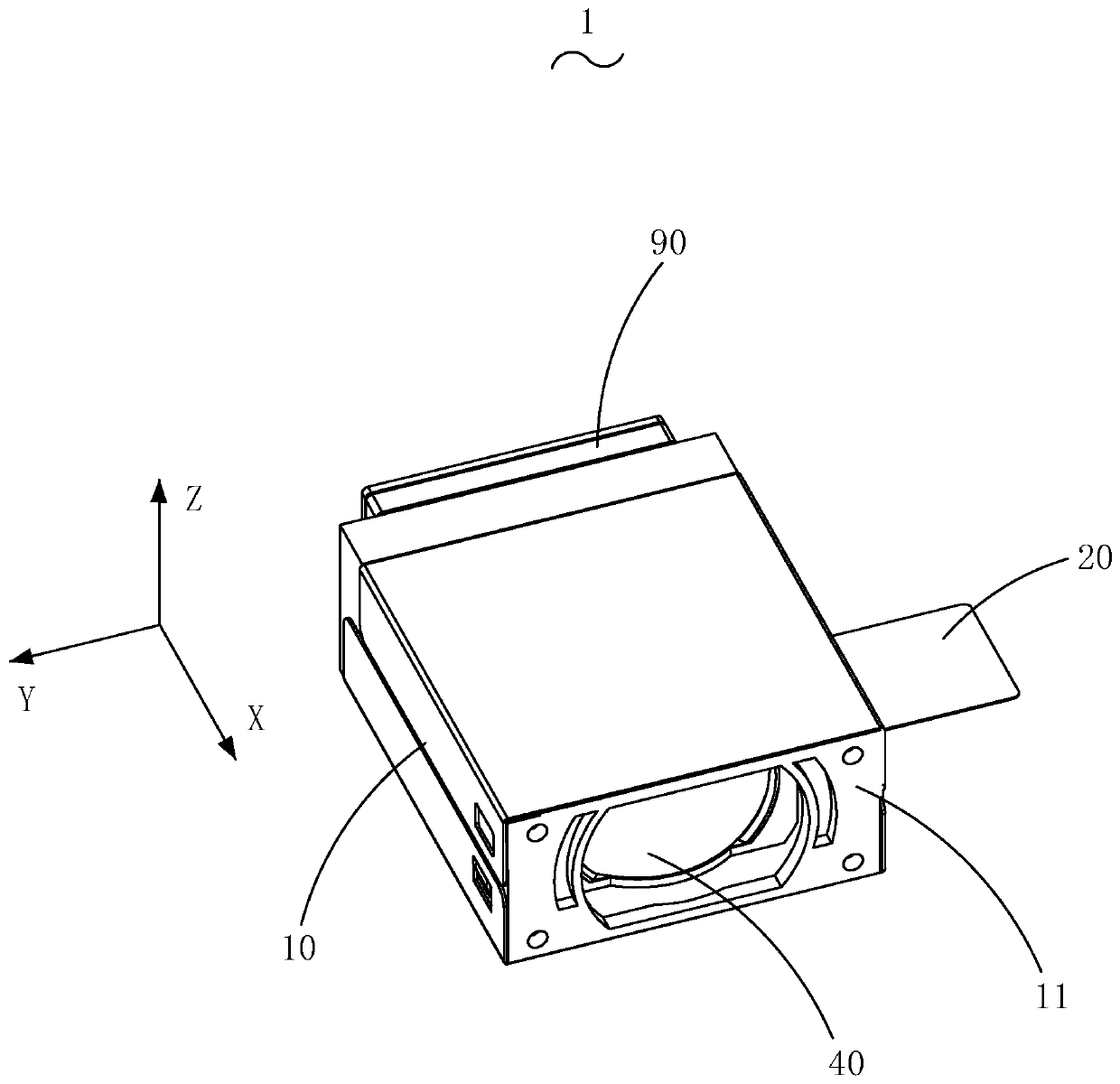
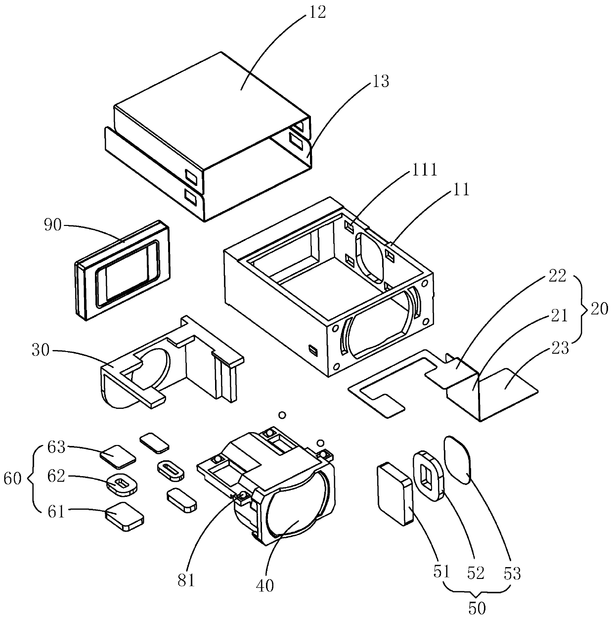
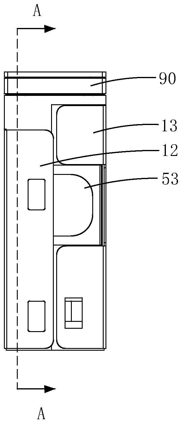
[0044] see Figure 1-17 , the embodiment of the present invention provides a lens lens module 1, the lens lens ...


PUM


Abstract

The invention provides a lens module of a lens; the lens module comprises a shell, a first support, a lens assembly, a focusing driving assembly and an anti-shake driving assembly, wherein the firstsupport is arranged in the shell in a manner of being movable relative to the shell along the optical axis direction of the lens assembly; the lens assembly is arranged in the first support in a manner that the lens assembly is movable relative to the first support in a direction perpendicular to the optical axis direction of the lens assembly and is not movable relative to the first support in adirection of the optical axis direction of the lens assembly; the focusing driving assembly is arranged on the shell and the first support so as to drive the first support to drive the lens assembly to move in the optical axis direction of the lens assembly; and the anti-shake driving assembly is arranged on the lens assembly and the shell so as to drive the lens assembly to move in a direction perpendicular to the optical axis direction of the lens assembly. The focusing driving assembly drives the first support to drive the lens assembly to move in the optical axis direction of the lens assembly so as to realize automatic focusing; and the anti-shake driving assembly drives the lens assembly to move in the direction perpendicular to the optical axis of the lens assembly so as to realizeanti-shake compensation.

Description

[0001] 【Technical field】 [0002] The invention relates to the technical field of optical imaging, in particular to a lens and lens module used in mobile electronic devices such as mobile phones. [0003] 【Background technique】 [0004] In recent years, with the development of imaging technology and the rise of electronic products with imaging functions, optical lenses are widely used in various electronic products. Generally, light is directly incident from the object side, passes through the lens assembly along the optical axis to the image side, and forms an image of the object through the lens assembly. However, in the prior art, the lens assembly has an auto-focus function. When shooting, the focus drive assembly can drive the lens assembly to move relative to the bracket along the optical axis to capture a clear image. However, in the case of shaking shooting, the lens assembly will move slightly in the plane perpendicular to the optical axis, which seriously affects the...

Claims


Application Information

Patent Timeline
Patent Type & Authority Applications(China)
IPC IPC(8): G02B7/09G02B7/10G03B13/36G03B5/00G03B30/00
CPCG02B7/09G02B7/10G03B13/36G03B5/00H02K41/0356G02B27/646G02B7/08G03B3/10G03B5/02G03B30/00G03B2205/0015G03B2205/0069
Inventor 徐同明赵后伟
Owner AAC OPTICS SOLUTIONS PTE LTD
Why Eureka
Eureka Blog
Learn More