
Wear-resistant mechanical timer

A mechanical timer and timer technology, which is applied in time program switches, electrical components, electric switches, etc., can solve the problems of high gear transmission accuracy and large gear transmission wear, so as to reduce wear and achieve timing. Effect

Inactive Publication Date: 2019-08-30
沙丽萍
View PDF9 Cites 2 Cited by
  • Summary
  • Abstract
  • Description
  • Claims
  • Application Information

AI Technical Summary

Problems solved by technology

[0003] Existing mechanical timers use too many gear transmissions, because the mechanical timers are used for timing, so the precision requirements for gear transmissions are too high, and the wear of gear transmissions is also relatively large. In view of the above problems, the present invention makes improvements

Method used


Image

  • Wear-resistant mechanical timer
  • Wear-resistant mechanical timer
  • Wear-resistant mechanical timer

Examples


Embodiment Construction

[0019] The following will clearly and completely describe the technical solutions in the embodiments of the present invention with reference to the accompanying drawings in the embodiments of the present invention. Obviously, the described embodiments are only some, not all, embodiments of the present invention. Based on the embodiments of the present invention, all other embodiments obtained by persons of ordinary skill in the art without making creative efforts belong to the protection scope of the present invention.

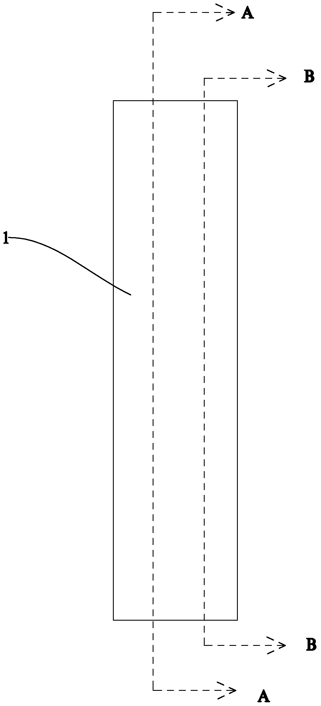
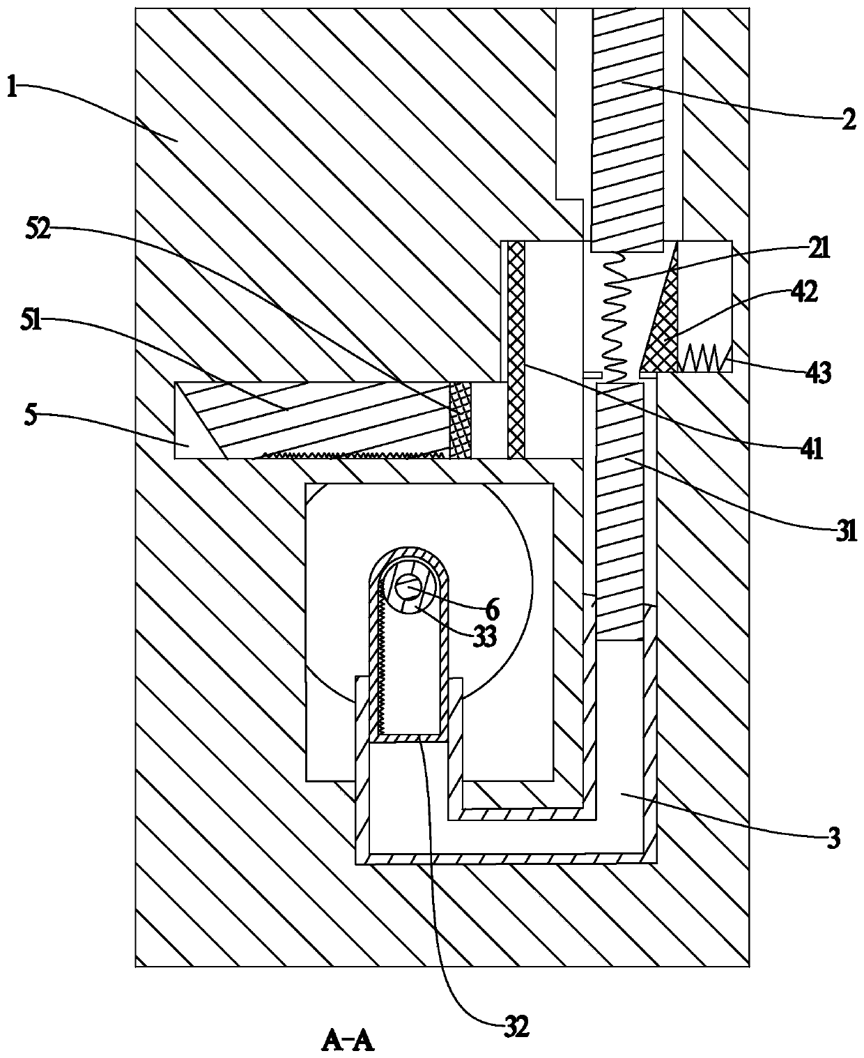
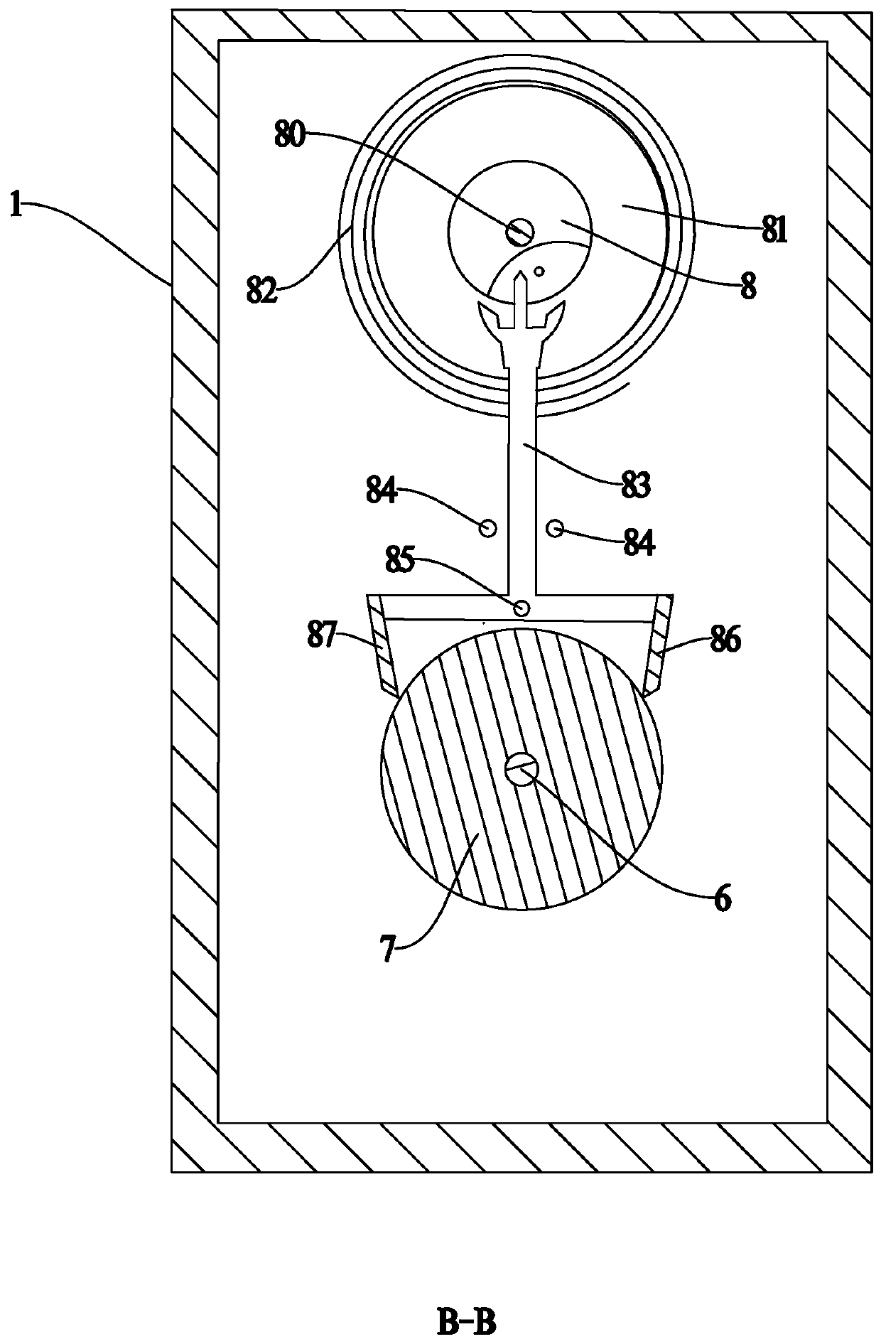
[0020] see Figure 1~6 , in the embodiment of the present invention, an anti-wear mechanical timer includes a timer housing 1, a vertically placed timing switch 2 is arranged inside the timer housing 1, and the top of the timing switch 2 is connected to the timer An elastic member 21 is fixed outside and at the bottom of the shell, and the elastic member can be any one of elastic members such as leaf springs, coil springs, torsion bar springs, gas springs, and...


PUM


Abstract

The invention discloses a wear-resistant mechanical timer. The wear-resistant mechanical timer comprises a timer shell, a timing switch which is vertically arranged is arranged in the timer shell, thetop end of the timing switch communicates with the outer portion of the timer shell, the bottom end of the timing switch is fixed with an elastic piece, the elastic piece is fixed at one end of a tight connection rod, the other end of the tight connection rod is connected with one side of the U-shaped pipe in a vertical sliding way, the other side of the U-shaped pipe is connected with a tight connection rack rail, one side of the inner ring of the tight connection rack rail is provided with teeth, the inside of the tight connection rack rail is provided with an arresting shaft fixed on the timer shell, the arresting shaft is provided with a gear meshed with the tight connection rack rail, an arresting mechanism is arranged on the arresting shaft and is connected on a moving block, the moving block is arranged on a horizontal channel, a conductive group is arranged on the channel and is connected to the timing switch, under the condition of reducing gears, the principle that the sealed inner volume of the U-shaped tube is not changed is selected, and an arresting wheel is driven to rotate by the energy storage of the elastic piece, so that the purpose of timing is achieved.

Description

technical field [0001] The invention relates to the technical field of timing, and in particular provides an anti-wear mechanical timer. Background technique [0002] Existing mechanical timers are mainly used in household accessories such as electric fans, heaters, heaters, water dispensers, clothes dryers, and pedicure instruments. Cut off circuit needs. [0003] Existing mechanical timers use too many gear transmissions, because the mechanical timers are used for timing, so the precision requirements for gear transmissions are too high, and the wear and tear of gear transmissions is also relatively large. In view of the above problems, the present invention makes improvements . Contents of the invention [0004] The purpose of the present invention is to provide an anti-wear mechanical timer to solve the problems raised in the background art above. [0005] To achieve the above object, the present invention provides the following technical solutions: [0006] An ant...

Claims


Application Information

Patent Timeline
IPC IPC(8): H01H43/02
CPCH01H43/02
Inventor 不公告发明人
Owner 沙丽萍
Learn More