

Integrated rotor axial force self-balance centrifugal pump, control method and terminal
An axial force, integrated technology, used in pump control, non-variable-capacity pumps, components of pumping devices for elastic fluids, etc., can solve problems such as short service life, wear, and fluid leakage of equipment, To achieve the effect of reducing fluid leakage, reducing wear and reducing wear problems
- Summary
- Abstract
- Description
- Claims
- Application Information
AI Technical Summary
Problems solved by technology
Method used
Image

Examples
Embodiment 1
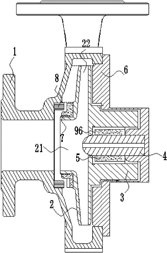
[0057] Please also refer to Figure 3-Figure 6 , this embodiment provides an integrated rotor axial force self-balancing centrifugal pump, including a pump body 1, an impeller 2, a rotor 3, a pump shaft 4, a bearing 5 and a spacer sleeve 6, specifically:
[0058] The impeller inlet 21 is provided with an impeller mouth ring 7, and the inner wall of the pump body 1 is provided with a pump body mouth ring 8 used in conjunction with the impeller mouth ring 7. The impeller mouth ring 7 rotates synchronously with the impeller 2, and is driven by the impeller 2 It moves in the axial direction to open or close the fluid passage between the impeller mouth ring 7 and the pump body mouth ring 8; the rotor 3 is connected to the end of the impeller 2 and has a cavity for accommodating the pump shaft 4 and the bearing 5, the rotor 3 There is a through hole near the side of the impeller 2, the pump shaft 4 passes through the through hole and enters the cavity; the spacer 6 covers the rotor ...
Embodiment 2
[0074] This embodiment provides a control method for the axial force self-balancing structure of the integrated rotor 3 in Embodiment 1, including the following steps:
[0075] Parameter setting: preset the positional relationship of each component, the fluid flow state and the flow gap between the components during the movement of the impeller 2;
[0076] Three-dimensional modeling: establish a three-dimensional model according to the positional relationship of each component, the fluid flow state and the flow gap between each component;
[0077] Simulation analysis: The simulation software analyzes the magnitude and direction of the axial force of the 3D model, and obtains the magnitude and direction data of the axial force;
[0078] Judgment analysis: judge whether the axial force magnitude data and direction data are within the preset range. When the axial force magnitude data or direction data exceeds the preset range, it is judged to re-perform the 3D modeling step, and ...
Embodiment 3
[0086]This embodiment provides a terminal for an integrated rotor axial force self-balancing centrifugal pump, including: a parameter setting module, a three-dimensional modeling module, a simulation analysis module, and a judgment analysis module;
[0087] The parameter setting module is used to: preset the positional relationship of each component, the fluid flow state and the flow gap between the components during the movement of the impeller 2;
[0088] The three-dimensional modeling module is used to: establish a three-dimensional model according to the positional relationship of each component, the fluid flow state and the flow gap between each component;
[0089] The simulation analysis module is used for: the simulation software analyzes the magnitude and direction of the axial force of the 3D model, and obtains the magnitude and direction data of the axial force;
[0090] The judgment analysis module is used to: judge whether the axial force magnitude data and directi...
PUM
 Abstract
Description
Claims
Application Information