Protective speed reducer

A technology of reducer and reduction mechanism, which is applied in the direction of mechanical equipment, transmission parts, gear transmission, etc., can solve the problems of lubricating oil and seal failure, reduce the service life of the reducer, improve work efficiency, etc., and achieve power utilization. The utilization rate of lubricating oil is improved, the wear problem is reduced, and the effect of compact structure

Inactive Publication Date: 2017-11-24
泰兴市通用减速机厂
View PDF0 Cites 2 Cited by
  • Summary
  • Abstract
  • Description
  • Claims
  • Application Information

AI Technical Summary

Problems solved by technology

[0002] Many of the current reducers are used in places where the working environment is relatively harsh. In this environment, they are likely to be damaged by external forces, resulting in damage to the reducer, which is not conducive to improving work efficiency.
However, since the transmission gear and transmission shaft of the reducer will w

Method used


Image

  • Protective speed reducer
  • Protective speed reducer
  • Protective speed reducer

Examples


Example Embodiment

[0014] The technical solutions in the embodiments of the present invention will be clearly and completely described below in conjunction with the accompanying drawings in the embodiments of the present invention. Obviously, the described embodiments are only a part of the embodiments of the present invention, rather than all the embodiments. Based on the embodiments of the present invention, all other embodiments obtained by those of ordinary skill in the art without creative work shall fall within the protection scope of the present invention.
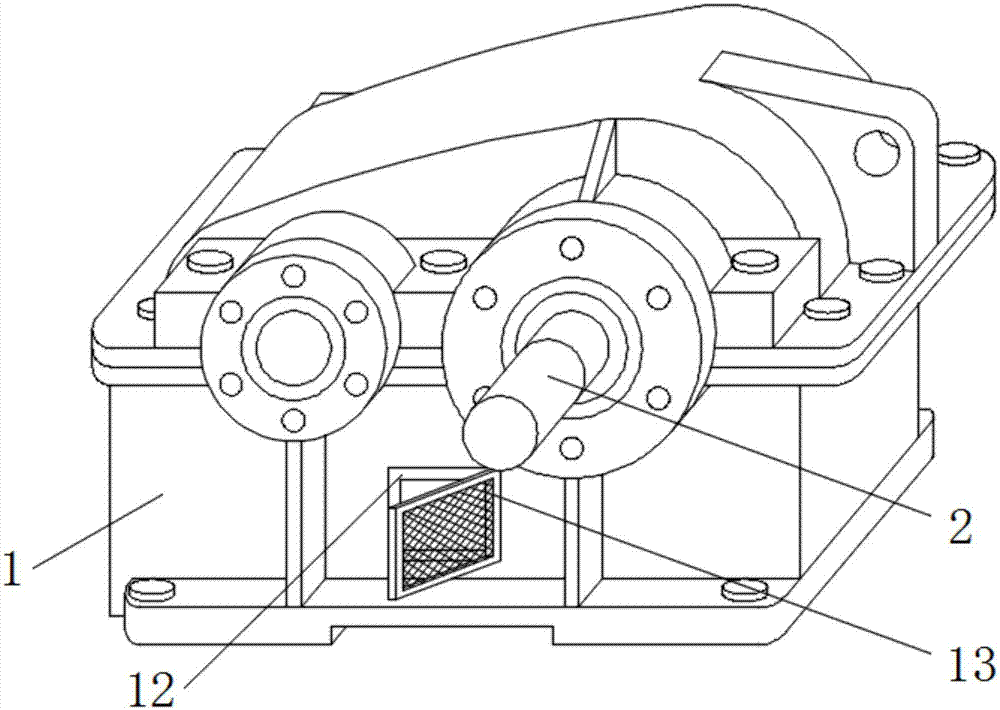
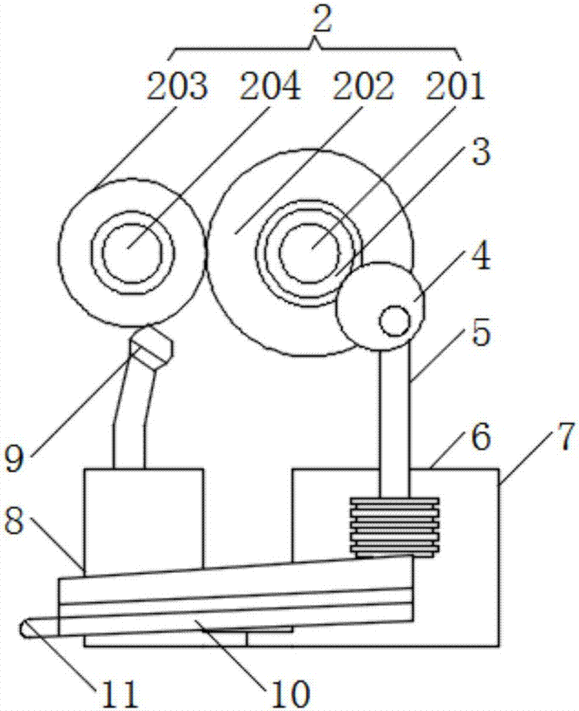
[0015] See figure 1 with figure 2 , The present invention provides a technical solution: a protective type reducer, including a housing 1 and a reduction mechanism 2, the inner cavity of the housing is provided with a reduction mechanism in the middle, the reduction mechanism includes a reduction drive shaft 201, The deceleration driving shaft is keyed with a deceleration driving gear 202. The outer side wall of the deceleration driving ...


PUM


Abstract

The invention discloses a protective reducer, which comprises a housing and a deceleration mechanism. A deceleration mechanism is provided in the middle of the inner cavity of the housing. Drive gear, the outer wall of the deceleration driving gear is meshed with a deceleration driven gear, the central part of the deceleration driven gear is connected to the deceleration driven shaft through a key, and the end face of the deceleration driving shaft located outside the housing is connected to the drive motor , the lubricating protection device of the present invention is placed inside the housing, reducing the opening of the housing itself, reducing the entry of foreign debris into the housing, while preventing the structure of the housing from being damaged, and using the same power device as the deceleration mechanism , compact structure, power utilization and lubricating oil utilization are effectively improved.

Description

technical field [0001] The invention relates to the technical field of reducers, and the specific field is a protective reducer. Background technique [0002] At present, many reducers are used in places with relatively harsh working environments. In this environment, they are likely to be damaged by external forces, resulting in damage to the reducer, which is not conducive to improving work efficiency. However, since the transmission gear and transmission shaft of the reducer will wear out with the increase of use time, especially in the production plant with harsh environment, the particulate matter will increase the wear of the reducer, thereby reducing the service life of the reducer; in addition, generally The lubricating oil and seals in the reducer will fail in a short time, which will affect the use of the reducer. Contents of the invention [0003] The purpose of the present invention is to provide a protective reducer to solve the problems raised in the above-m...

Claims


Application Information

Patent Timeline
IPC IPC(8): F16H1/04F16H57/04
CPCF16H1/04F16H57/0435F16H57/0446F16H57/0456
Inventor 殷新晋
Owner 泰兴市通用减速机厂
Why Eureka
Try Eureka