Exhaust gas after treatment system and method for operating an exhaust gas after treatment system for internal combustion engine

Inactive Publication Date: 2009-01-29
MAZDA MOTOR
View PDF12 Cites 23 Cited by
  • Summary
  • Abstract
  • Description
  • Claims
  • Application Information

AI Technical Summary

Benefits of technology

[0004]One system for addressing this issue is described in JP2003-232218. In this reference, a mixing element for facilitating mixing of a urea aqueous solution injected from an injection nozzle with exhaust gas is provided in an exhaust passage located between the urea injection nozzle and a selective reduction catalyst. This mixing element comprises a division plate on which an opening is formed having a smaller cross-sectional area than a cross-sectional area of the plate. When exhaust gases contact the division plate and pass through the opening, the exhaust flow is disturbed. This causes the injected aqueous urea solution to mix well within the exhaust ga

Problems solved by technology

This can decrease engine torque performan

Method used


Image

  • Exhaust gas after treatment system and method for operating an exhaust gas after treatment system for internal combustion engine
  • Exhaust gas after treatment system and method for operating an exhaust gas after treatment system for internal combustion engine
  • Exhaust gas after treatment system and method for operating an exhaust gas after treatment system for internal combustion engine

Examples


Example

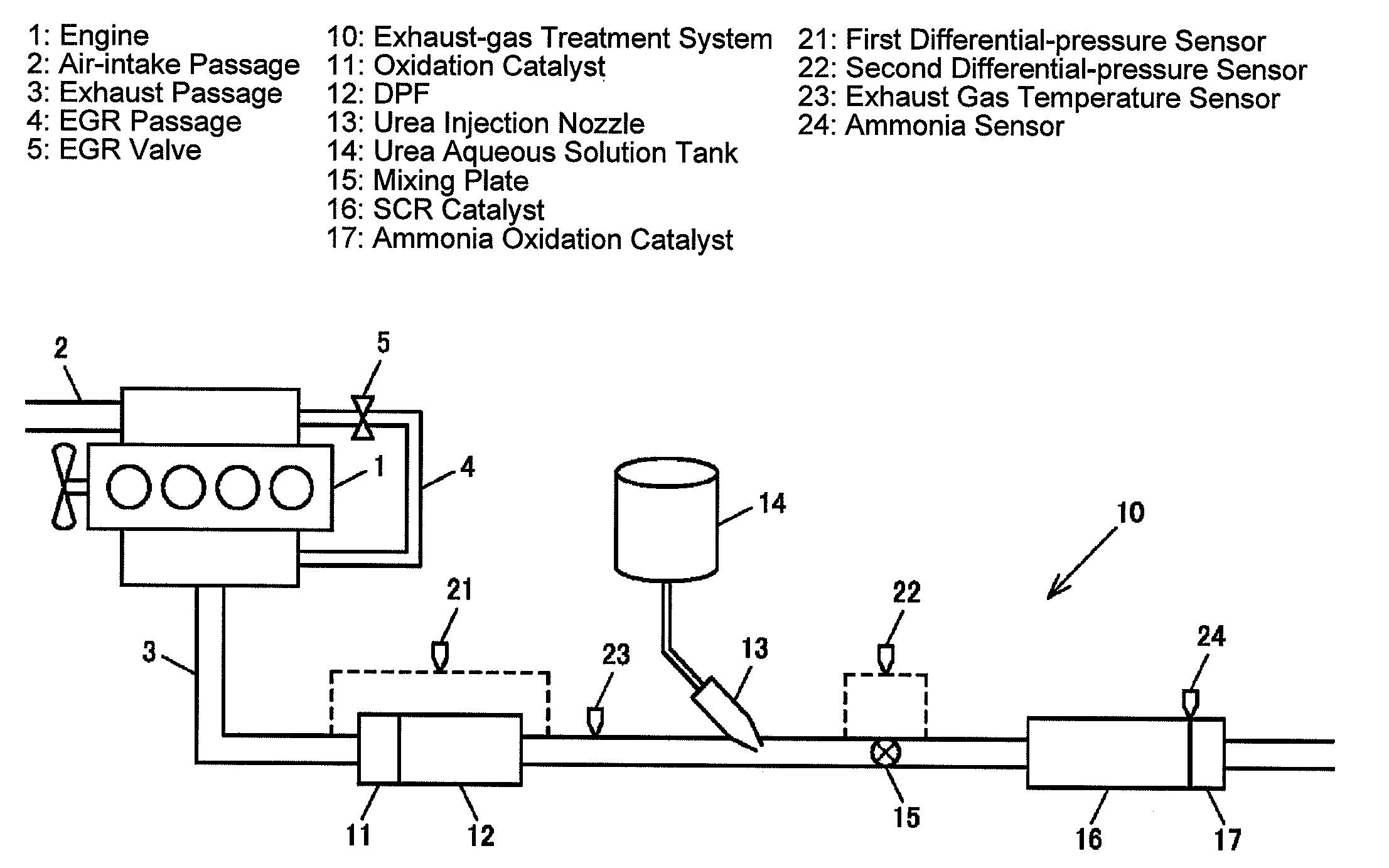
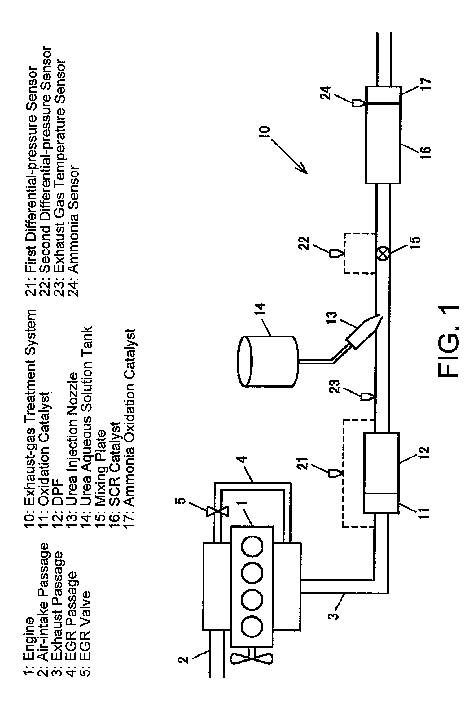
[0021]FIG. 1 is a schematic view showing an entire exhaust-gas treatment system 10 of an internal combustion engine 1 according to an embodiment of the present invention. In this embodiment, the engine 1 is a diesel engine, and includes an air-intake passage 2, an exhaust passage 3, an EGR passage 4 that allows a portion of the exhaust gas to return to an air-intake side, and an EGR valve 5 provided in the EGR passage 4.

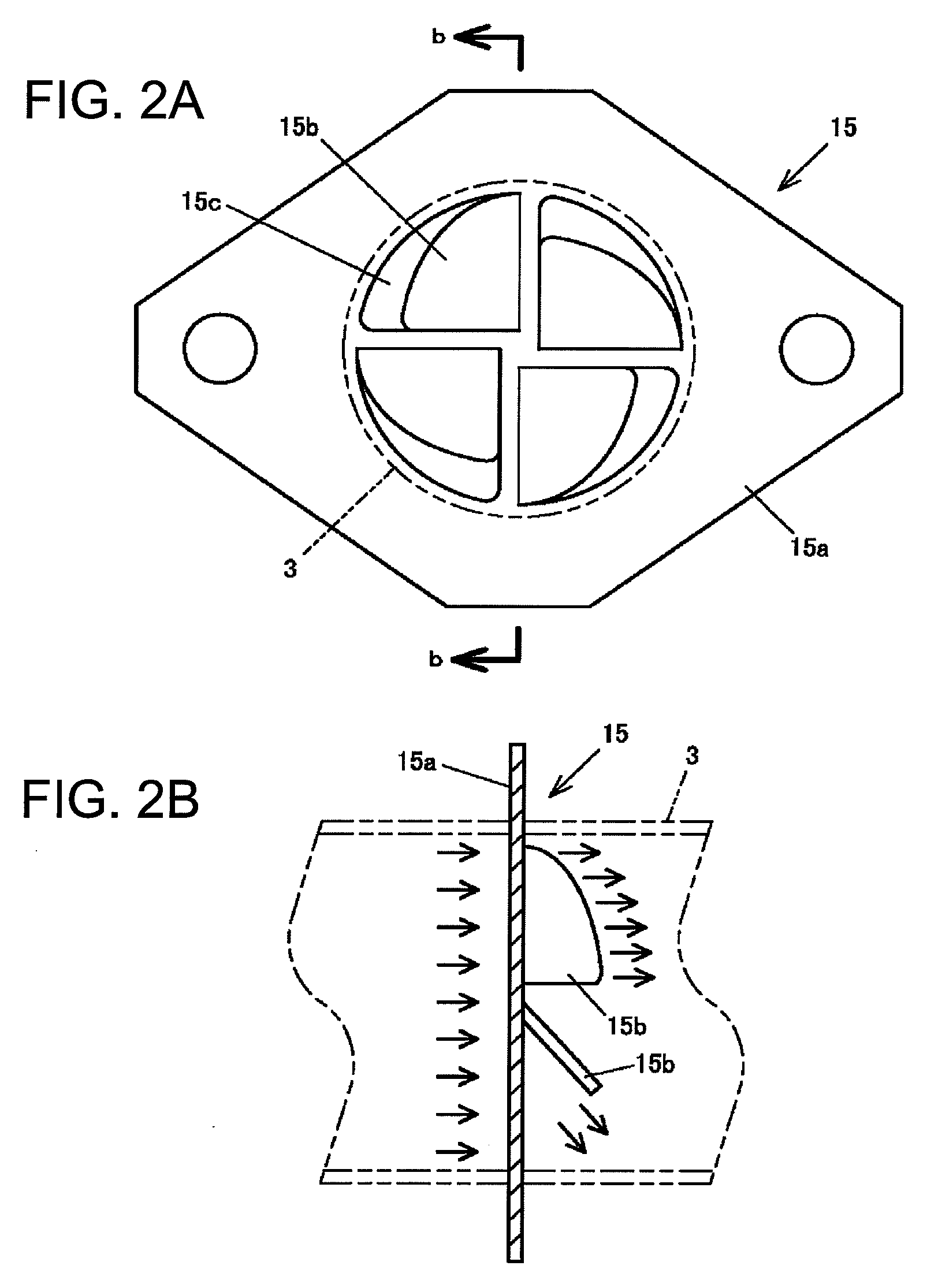
[0022]In the exhaust passage 3, from an upstream side, an oxidation catalyst 11 for oxidizing to burn unburnt fuel contained in the exhaust gas, a diesel particulate filter element (DPF) 12 for collecting particulates contained in the exhaust gas, a urea injection nozzle 13 for injecting urea aqueous solution supplied from in a urea aqueous solution tank 14 into the exhaust passage 3, a mixing plate 15 for stimulating mixing of the urea aqueous solution injected from the injection nozzle 13 with the exhaust gas, a selective reduction (SCR) catalyst 16 for selectively...


PUM

PropertyMeasurementUnit
Temperatureaaaaaaaaaa
Timeaaaaaaaaaa
Pressureaaaaaaaaaa

Abstract

A system for controlling performance of an internal combustion engine. The system may include an internal combustion engine having an exhaust system for processing gases exhausted from the internal combustion engine. The exhaust system may be comprised of at least one mixing device, at least one emission control device, and a delivery apparatus for delivering an agent affecting operation of the emission control device into the exhaust system. The at least one mixing device may be located downstream of the internal combustion engine and upstream of the at least one emission control device, and the delivery apparatus may be located upstream of the emission control device. The system may include a controller to adjust at least one engine parameter in relation to an operating condition of the mixing device.

Description

TECHNICAL FIELD[0001]The present description relates to an exhaust-gas treatment system and a method for operating an exhaust-gas treatment system for an internal combustion engine. More particularly, the description pertains to an exhaust-gas treatment system and a method for operating the exhaust-gas treatment system in order to decrease nitrogen oxide (NOx) that may be contained in emissions from an internal combustion engine.BACKGROUND AND SUMMARY[0002]Urea-SCR (Selective Catalytic Reduction) systems are a known technology for decreasing NOx contained in the emissions from an internal combustion engine. Often, a selective reduction catalyst is placed in an engine exhaust passage to reduce NOx in the exhaust gases. A urea aqueous solution injection nozzle is placed upstream of the selective reduction catalyst for injecting urea (or urea reductants) into the exhaust stream. The injected urea is thermally decomposed or hydrolyzed into ammonia by heat from exhaust gas. Then, the amm...

Claims


Application Information

Patent Timeline
IPC IPC(8): F01N3/18F02D41/34F02D41/40
CPCB01F3/04049B01F5/0451B01F5/0616F01N3/206F01N9/002F01N11/002Y02T10/24F01N2430/08F01N2560/08F01N2610/02F02D41/0245Y02T10/26Y02T10/47F01N2240/20Y02T10/12Y02T10/40B01F23/2132B01F25/3131B01F25/4315
Inventor SAKIMOTO, MASATSUGUYAMADA, HIROSHIISHIDA, HIROAKI
Owner MAZDA MOTOR
Why Eureka
Try Eureka