Method of manufacturing solar panel

Inactive Publication Date: 2008-05-29
MITSUBISHI HEAVY IND LTD
View PDF21 Cites 9 Cited by
  • Summary
  • Abstract
  • Description
  • Claims
  • Application Information

AI Technical Summary

Benefits of technology

[0013]Therefore, an object of the present invention is to provide a method of manufacturing a solar cell panel capable of p

Problems solved by technology

Thus, this results in a decrease in the electric power generation.
The large variation in the results and the output decrease in the solar cell panels cause a reduction in a manufacturing yield of t

Method used


Image

  • Method of manufacturing solar panel
  • Method of manufacturing solar panel
  • Method of manufacturing solar panel

Examples


Example

Comparative Example 1

[0074]The comparative examples 1 refer to solar cell panel substrates subjected to the inspection of the electric power generation (step S50) between times t1 and t2. For the solar cell panel substrate of the comparative example 1, the cleaning processing (step S40) is not performed.

Example

Comparative Example 2

[0075]The comparative examples 2 refer to solar cell panel substrates subjected to the inspection of the electric power generation (step S50) between times t2 and t3. For the solar cell panel substrate of the comparative example 2, cleaning in the cleaning processing performed before the inspection of the electric power generation on the solar cell module (step S20) is enhanced. Specifically, for the pressured water showering and roll brush washing performed between the back-electrode-layer forming device 16 and the laser etching device 17, a distance between the roll brush and the solar cell panel substrate is reduced by a small amount to thereby increase the roll brush pushing pressure. For embodiments 1 to 3, cleaning between the back-electrode-layer forming device 16 and the back surface laser etching device 17 is performed by similarly increasing the roll brush pushing pressure.

Example

Embodiment 1

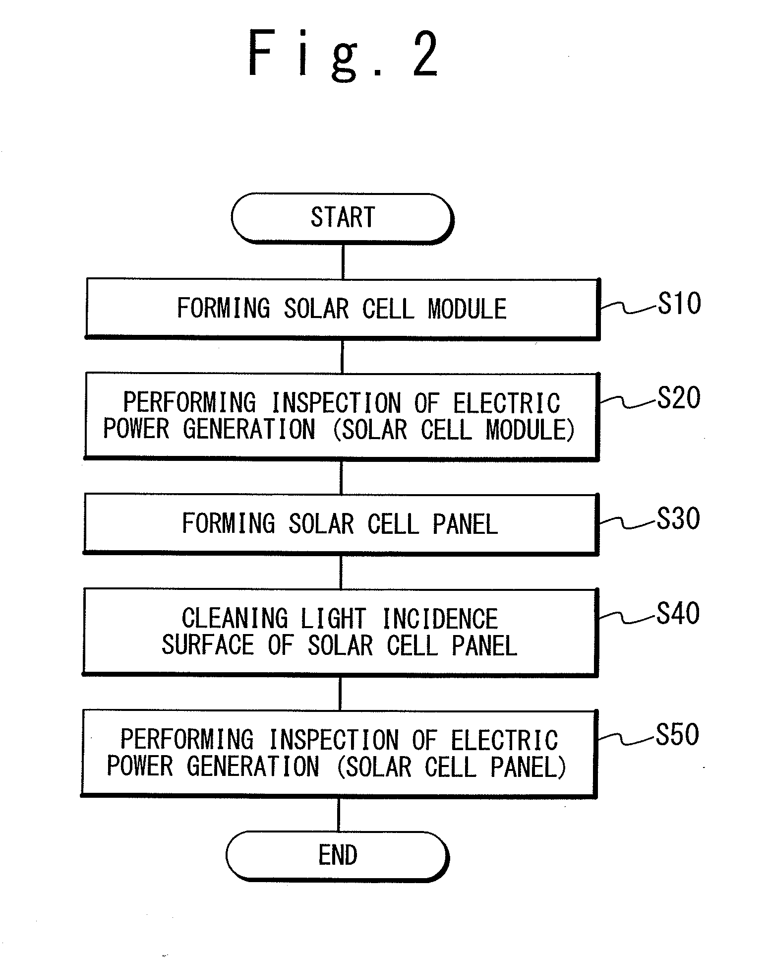
[0076]The embodiments 1 refer to solar cell panel substrates subjected to the inspection of the electric power generation (step S50) between times t4 and t5. For the solar cell panel substrate of the embodiment 1, cleaning of physically wiping the light incidence surface (step S40) is performed immediately before the inspection of the electric power generation (step S50). The cleaning (step S40) is achieved by installing nonwoven fabric in a carrying line and then wiping the light incidence surface while pushing the nonwoven fabric against the light incidence surface. Bemcot (product name: manufactured by ASAHI KASEI FIBERS CORPORATION) is used as the nonwoven fabric.


PUM

PropertyMeasurementUnit
Lengthaaaaaaaaaa
Lengthaaaaaaaaaa
Fractionaaaaaaaaaa

Abstract

A method of manufacturing a solar cell panel, includes steps (a) to (e). The step (a) is a step of forming a solar cell module by laminating solar cell films on a transparency substrate. The step (b) is a step of performing an inspection of electric power generation on the solar cell module. The step (c) is a step of forming a solar cell panel by executing a panel formation on the solar cell module. The step (d) is a step of cleaning a light incidence surface of the solar cell panel. The step (e) is a step of performing an inspection of electric power generation on the solar cell panel. The step (d) is executed immediately before the step (e).

Description

BACKGROUND OF THE INVENTION[0001]1. Field of the Invention[0002]The present invention relates to a method of manufacturing a solar cell panel.[0003]2. Description of Related Art[0004]A method of manufacturing a solar cell panel is known, wherein the solar cell panel generates electric power by receiving sunlight. The method of manufacturing the solar cell panel includes: a process of forming a solar cell module; and a process of forming a panel using the solar cell module. In the process of forming the solar cell module, films used for solar cells are laminated on a transparency substrate and patterned by using laser etching or the like into a plurality of solar cells, which are integrated with series junctions. In the panel forming process, removal of the films located in a non-power-generating region, attachment of a cover sheet or the like, fitting of wires and a terminal box for drawing electric power, and the like are performed on the solar cell module to form a panel using the...

Claims


Application Information

Patent Timeline
IPC IPC(8): C23F1/00B32B38/00
CPCH01L31/042H01L31/046Y02E10/50H01L31/186H02S50/00H02S50/15Y02P70/50
Inventor SONOBE, HIROSHITAKANO, AKEMINAWATA, YOSHIKAZUUCHIHASHI, KAZUMASAOGAWA, KAZUHIKOYAMANE, TSUKASAYAMASHITA, NOBUKI
Owner MITSUBISHI HEAVY IND LTD
Why Eureka
Try Eureka