Rapid fixing type paying-off construction process

A construction technology and fast technology, applied in electrical components, transportation of filamentous materials, cable laying equipment, etc., can solve the problems of scattered cable coils, slow cable pay-off speed, and high labor intensity, and reduce labor costs. cost, increase the speed of the pay-off, and facilitate the effect of limiting the effect

Active Publication Date: 2019-09-06
CHONGQING CONSTR NINTH ENG
View PDF14 Cites 3 Cited by
  • Summary
  • Abstract
  • Description
  • Claims
  • Application Information

AI Technical Summary

Problems solved by technology

[0006] The present invention intends to provide a fast fixed pay-off construction process to solve the problems in the prior art that the cable rolls are scattered, the cable pay-off speed is slow, and the labor intensity is high

Method used


Image

  • Rapid fixing type paying-off construction process
  • Rapid fixing type paying-off construction process
  • Rapid fixing type paying-off construction process

Examples


Embodiment 1

[0046] Embodiment one is basically as Figure 1 to Figure 6 Shown:

[0047] The fast fixing and setting-out construction technology includes the following steps:

[0048] Step 1, take the fast fixed pay-off device:

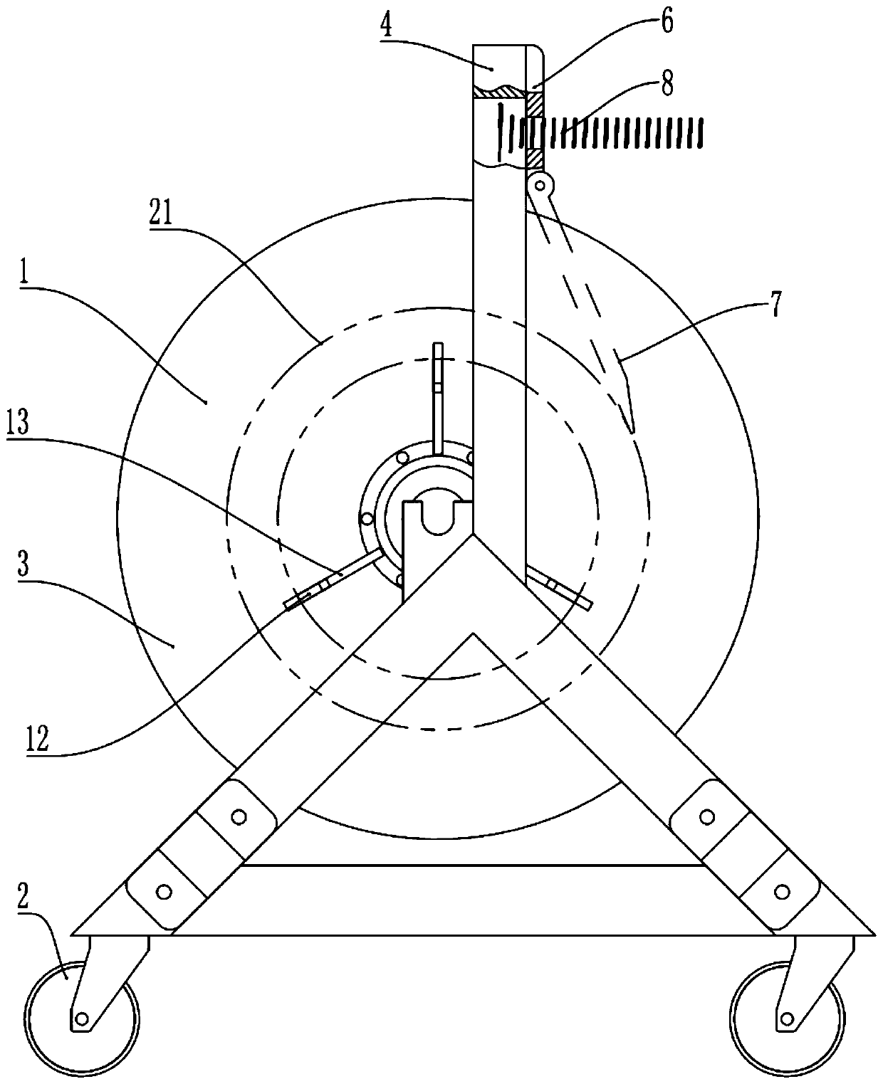
[0049] combine figure 1 and figure 2 , Quickly fix the pay-off device, including a bracket and three wire loading reels 1, the wire loading reels 1 are rotatably connected to the bracket, and casters 2 are installed at the bottom of the bracket. The support includes a main support frame 3 and a cross bar 4. The main support frame 3 is provided with a slot part 5, and a partition is arranged inside the slot part 5, and the partition divides the slot part 5 into two slots.

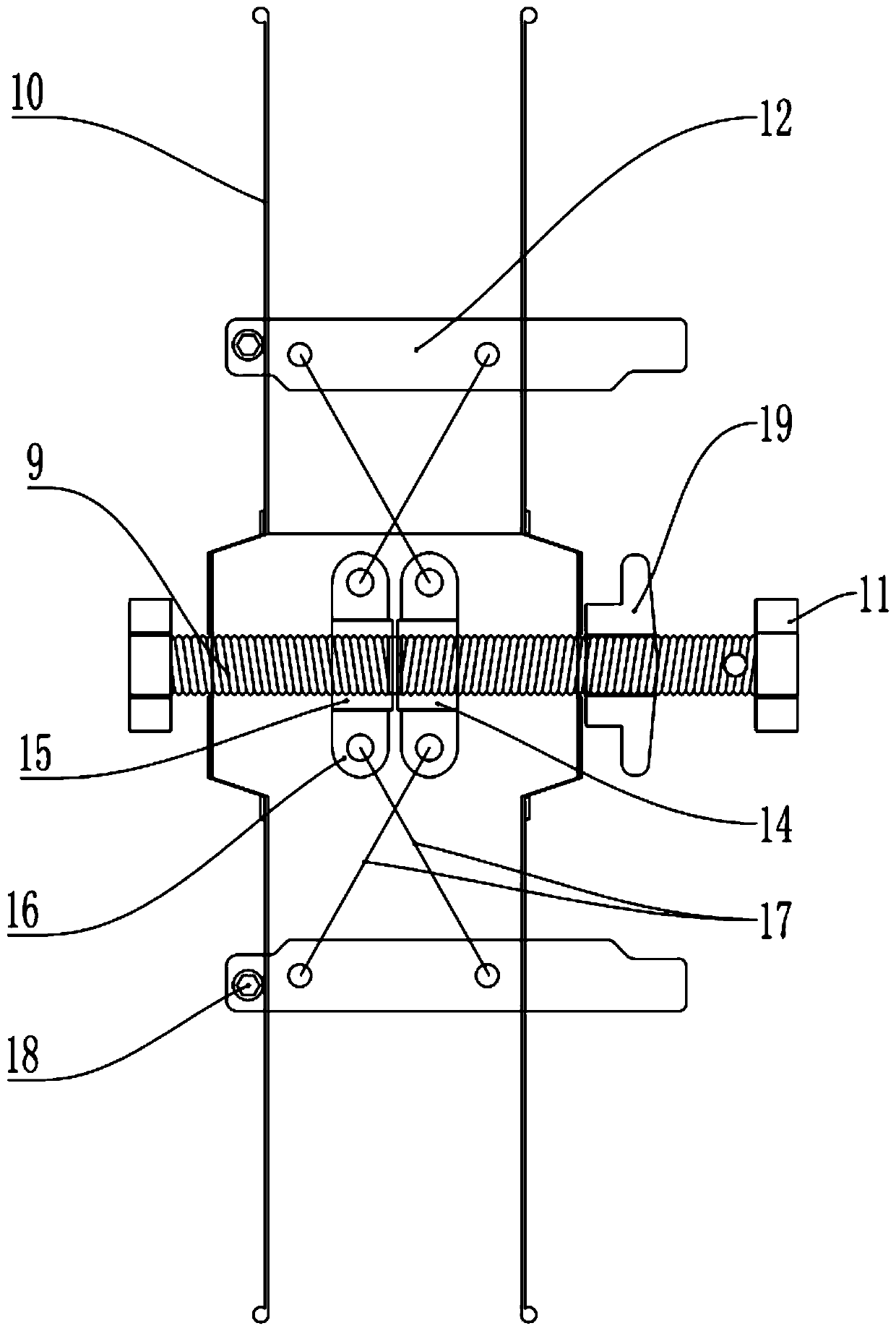
[0050] The crossbar 4 is connected to the main support frame 3 by bolts, the crossbar 4 is located above the wire loading tray 1, and a waist-shaped hole is opened on the crossbar 4; a brake unit is connected to the crossbar 4, and the brake unit includes a connecting plate 6 and a brake T...

Embodiment 2

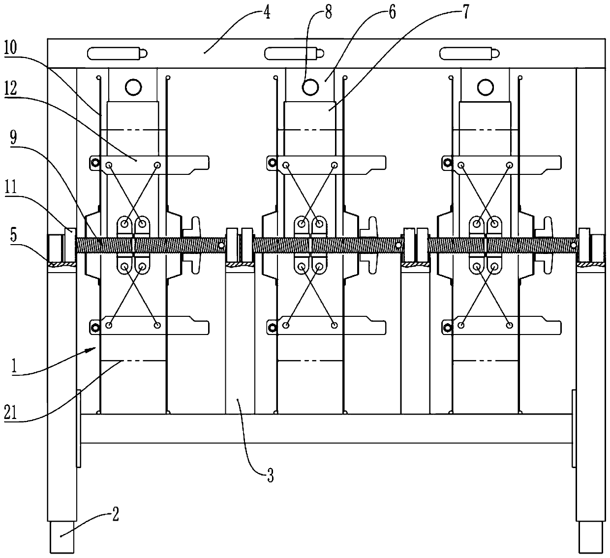
[0068] Embodiment two is basically as Figure 7 Shown; Embodiment two is on the basis of embodiment one, has also increased following steps:

[0069] Step 5, increase the number of wiring reels 1:

[0070] Install external brackets 20 through screws at both ends of the cross bar 4, take the wire loading reel 1 where the cable coil 21 is installed in step 2 of the first embodiment, and connect one end of the screw rod 9 on the wire loading reel 1 to the external bracket by rotating On the slot part 5 of the frame 20, the other end of the screw mandrel 9 is rotatably connected to the slot part 5 of the support, for the wire reel 1 that is completed in addition.

[0071] By setting the external bracket 20, on the basis of the existing embodiment one, the external bracket 20 for installing the wire reel 1 can also be added on the left and right sides of the cross bar 4, so that the entire device can be installed. The number of cable reels 1 is increased by two, the utilization r...


PUM


Abstract

The invention relates to the technical field of electric power paying-off, and particularly discloses a rapid fixing type paying-off construction process. The rapid fixing type paying-off constructionprocess comprises the following steps that S1, a rapid fixing type paying-off device is taken, wherein the rapid fixing type paying-off device comprises a support and a cable installing disc, the cable installing disc is rotationally connected to the support, and the cable installing disc comprises a supporting shaft and two baffle discs which are distributed in the axial direction of the supporting shaft; S2, a cable coil is installed, wherein the cable installing disc is taken down from the support, the baffle discs are taken down from the cable installing disc, the cable coil which needs to be installed sleeves expanding rods, then the taken-down baffle discs are installed back, stretching and retracting units are adjusted, so that the inner ring of the cable coil is tightened throughthe expanding rods, the baffle discs are adjusted, so that the baffle discs tightly press against the two sides of the cable coil, and the cable installing disc are installed on the support; and S3, paying-off is prepared, wherein a cable head of the outer ring of the cable coil is sorted out, and a section of cable is pulled out for later use. According to the scheme, the problems that the cablecoil is scattered, the paying-off speed of the cable is low and the manual labor intensity is large in the prior art are solved through the cable installing disc, the stretching and retracting units and the expanding rods.

Description

technical field [0001] The invention relates to the technical field of electric power setting out, in particular to a fast fixed setting out construction technology. Background technique [0002] In the construction process of electric low-voltage indoor wiring, indoor integrated wiring, building security, etc., cable laying work accounts for about 30% of the project volume. Existing cables are generally cable rolls wound into rolls (the outer surface of the cable roll is generally covered with plastic film or cable ties are tied on the cable roll to ensure that the cable roll will not be loose). There are generally two ways to take the cable from the cable reel, one is to take it from the outer coil of the cable coil, and the other is to take it from the inner coil of the cable coil. [0003] When the cable is taken from the outer ring of the cable roll, the cable roll is usually placed on a support rod with an outer diameter smaller than the inner ring of the cable roll. ...

Claims


Application Information

Patent Timeline
Patent Type & Authority Applications(China)
IPC IPC(8): B65H49/32B65H49/36B65H49/20B65H49/34B65H57/08H02G1/06H02G3/00
CPCB65H49/20B65H49/324B65H49/34B65H49/36B65H57/08B65H2403/61B65H2701/34H02G1/06H02G3/00
Inventor 梁伟郑自华郭长春周雪梅梁波
Owner CHONGQING CONSTR NINTH ENG
Why Eureka
Try Eureka