Air inlet channel structure and manufacturing method thereof

A manufacturing method and a technology of an air inlet, which are applied in the direction of fuel air inlet, combustion air/combustion-air treatment, engine components, etc., can solve problems such as energy consumption, flow separation method and mechanism complexity, and achieve wide applicability, Realize the effect of flow drag reduction and improve the effect of flow drag reduction

Inactive Publication Date: 2019-09-06
INST OF ENGINEERING THERMOPHYSICS - CHINESE ACAD OF SCI
View PDF5 Cites 4 Cited by
  • Summary
  • Abstract
  • Description
  • Claims
  • Application Information

AI Technical Summary

Problems solved by technology

[0005] Aiming at the existing technical problems, the present invention proposes an air inlet structure and its manufacturing method, which are used to solve the problems of complicated mechanisms and energy consumption in the existing control flow separation methods

Method used


Image

  • Air inlet channel structure and manufacturing method thereof
  • Air inlet channel structure and manufacturing method thereof
  • Air inlet channel structure and manufacturing method thereof

Examples


Embodiment Construction

[0033] In order to make the object, technical solution and advantages of the present invention clearer, the present invention will be described in further detail below in conjunction with specific embodiments and with reference to the accompanying drawings.

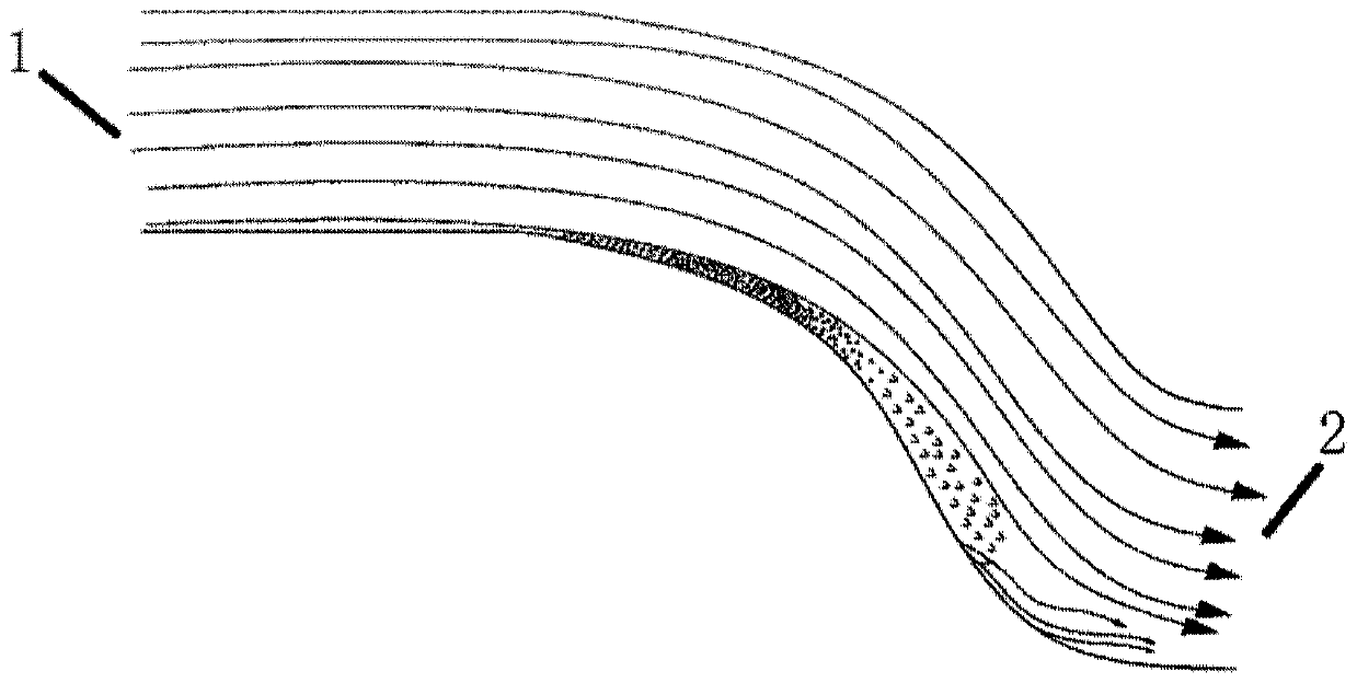
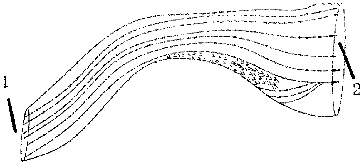
[0034] figure 1 with figure 2 They are the schematic diagrams of the existing typical S-curved inlet structure and the serpentine inlet structure respectively. It can be clearly seen from the figure that this inlet structure has an obvious boundary layer separation zone, and the separation zone will be at the exit. It evolves into a strong vortex distortion flow field, which affects the working performance of the engine body. From the perspective of the principle of boundary layer separation flow control, the purpose is to increase the ability of the boundary layer to resist the adverse pressure gradient. If the energy dissipation of the flow near the wall can be reduced by reducing the flow resistance, the boundary lay...


PUM


Abstract

The invention discloses an air inlet channel structure and a manufacturing method thereof. The air inlet channel structure is S-shaped or serpentine, a plurality of shark skin scale-shaped structuresare arranged on the inner wall of the air inlet channel structure, the shark skin scale-shaped structures are arranged in an array mode in the circumferential direction or the axial direction of the air inlet channel structure, and the arrayed array density is different, when axial arrangement is conducted, the array density arranged at the two sides of a large bent angle in the arraying mode is larger than that of the array arranged in the other areas in the arraying mode. According to the air inlet channel structure, the separation flow of a boundary layer of the air inlet channel is controlled, the problems that an existing air inlet channel flow control mode needs to increase additional energy and an auxiliary mechanism as well as the self-adaptive performance is poor are solved; and the circumferential or axial array arrangement mode of the shark skin scale-shaped structures can inhibit the flow separation of the boundary layer in a maximal and continuous mode, and the air inlet channel structure is wider in applicability.

Description

technical field [0001] The invention relates to the technical field of gas turbines, in particular to an air inlet structure and a manufacturing method thereof. Background technique [0002] The S-curve or serpentine inlet is one of the important parts of military engines. It can not only shorten the length of the inlet and improve the thrust-to-weight ratio, but also has good stealth. However, the S-curve or serpentine inlet has a large bend The angular structure will generate flow resistance to the high-speed inlet airflow. The S-shaped pipe expands along the flow direction and there is a large reverse pressure gradient. The high-speed airflow entering the intake pipe is difficult to attach to the inner wall of the extremely curved pipe, and flow separation is prone to occur. At the same time, due to the fact that there are two bends in different directions, when the main air flow passes through these two bends, due to the action of centrifugal force, the distribution of t...

Claims


Application Information

Patent Timeline
Patent Type & Authority Applications(China)
IPC IPC(8): F02M35/104F02M35/10
CPCF02M35/10111F02M35/104
Inventor 李继超李智慧杜娟刘洋李帆张宏武
Owner INST OF ENGINEERING THERMOPHYSICS - CHINESE ACAD OF SCI
Why Eureka
Try Eureka