An annular inner tube and an installation method thereof

An installation method and annular technology, applied in tire parts, transportation and packaging, reinforcement layers of pneumatic tires, etc., can solve the problems of difficult installation and disassembly, long time consumption, and easy occurrence of danger. The effect of ensuring continued safe driving

Inactive Publication Date: 2019-09-13
MAANSHAN TUHAOXIN TIRE TECH DEV
View PDF0 Cites 0 Cited by
  • Summary
  • Abstract
  • Description
  • Claims
  • Application Information

AI Technical Summary

Problems solved by technology

[0002] At present, most automobiles, cars, motorcycles, etc. use steel wheels or aluminum alloy wheels, which are divided into wheels with gallbladder and wheels without gallbladder. When such wheels blow out during driving, the direction of the car will lose control, which is prone to danger.
The support rings in the prior art are all installed on the wheel grooves. Therefore, the support rings in the prior art take a long time in the installation process, and it is very difficult to install and disassemble, which brings a lot of troubles to the car owner and maintenance personnel. troubled

Method used


Image

  • An annular inner tube and an installation method thereof
  • An annular inner tube and an installation method thereof
  • An annular inner tube and an installation method thereof

Examples


Embodiment 1

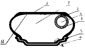
[0021] Example 1: from figure 1 , is made up of cover tire 1, wheel 5, valve 4, is provided with annular inner tube 2 on the inner surface of cover tire 1, and this annular inner tube 2 is provided with inflatable cavity, and annular inner tube 2 is provided with valve 3, and the diameter of annular inner tube is consistent with the diameter of cover tire inner surface Correspondingly, the annular inner tube 2 is supported on the left inner surface or the right inner surface of the inner surface of the tire, and the annular inner tube 2 can support the outer tire in an inflated state.

Embodiment 2

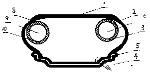
[0022] Example 2: From figure 1 , Figure 11 , is made up of cover tire 1, wheel 5, valve 4, is provided with annular inner tube 3 on the left inner surface of outer tire 1 or right inner surface, and the inner surface of annular inner tube 2 is provided with annular self-repairing rubber layer, and tire repairing rubber layer is a kind of adhesive Adhesive layer, the annular self-sealing rubber adhesive layer is arranged on the inner surface of the annular inner tube, and the annular inner tire 2 is in the state of air leakage. The annular tire repair rubber layer will be blocked by the air pressure in the cavity and bonded to the leak hole of the annular inner tube. The inner tube 2 is provided with an inflation cavity, the annular inner tube 2 is provided with a valve 3, the diameter of the annular inner tube coincides with the diameter of the inner surface of the outer tire, the annular inner tube 2 is supported on the inner surface of the left side of the upper part of th...

Embodiment 3

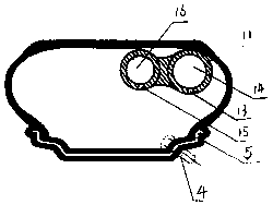
[0023] Example 3: from figure 1 , Figure 8 The inner surface side of cover tire 1 installs annular inner tube 2, and this annular inner tube 2 is provided with inflation cavity, and annular inner tube 2 is provided with air valve, and annular inner tube diameter coincides with cover tire inner surface diameter, can support cover tire under annular inner tube 2 inflated state, The annular inner tube 2 is provided with an annular ply, wherein the annular ply is a folded annular ply, and there is also an interval folded annular ply, wherein there are multiple annular inner tube supports in the outer tire, the inner diameter of the annular inner tube 2 is larger than the inner diameter of the outer tire, and the annular Inner tube of a tube 2 is installed on the left side or right side of cover tire inner surface diameter.


PUM


Abstract

An annular inner tube and an installation method thereof are provided. According to the present invention, since a cover tire and an annular inner tube are installed in sequence, and the cover tire annular inner tube is preliminarily held in the shape of 8 in advance and installed to the inner surface of the cover tire, the integral annular inner tube can be quickly installed and matched in a skillful mode, and the problems of long installation time and the influence on tire balancing in the prior art are solved. The technical method achieves the effect that the annular inner tube facilitatesquick installation. Compared with the prior art, the technical method completely solves the installation problem and the balance problem of tires, making the disassembly and repair more convenient. When the annular inner tube is installed on the surface of the cover tire, the automobile tire has a performance guarantee for safe driving. In the state where the cover tire is deflated, the annular inner tube can play the role of supporting the cover tire to continue driving, so the safe driving can be ensured when a tire bursts during high-speed driving of an automobile.

Description

technical field [0001] The invention relates to an inner tube, in particular to an annular inner tube and its installation method. Background technique [0002] At present, most automobiles, cars, motorcycles, etc. use steel wheels or aluminum alloy wheels, which are divided into wheels with gallbladder and wheels without gallbladder. If this type of wheel blows out during driving, the direction of the car will lose control, which is prone to danger. . The support rings in the prior art are all installed on the wheel grooves. Therefore, the support rings in the prior art take a long time in the installation process, and it is very difficult to install and disassemble, which brings a lot of troubles to the car owner and maintenance personnel. troubled. Contents of the invention [0003] The purpose of the present invention is to solve the above problems and provide a ring-shaped inner tube with a simple structure that can continue to run safely after a tire blowout, and a...

Claims


Application Information

Patent Timeline
IPC IPC(8): B60C17/01B60C5/10B60C5/22B60C9/26
CPCB60C5/10B60C5/22B60C9/26B60C17/01
Inventor 杜正林
Owner MAANSHAN TUHAOXIN TIRE TECH DEV
Why Eureka
Try Eureka