Modular support frame for solar power assembly

a solar power and module technology, applied in the field of solar power technology, can solve the problems of high cost, high installation difficulty, time-consuming and difficult application, etc., and achieve the effect of convenient and quick installation of solar power assemblies

Pending Publication Date: 2021-07-01
JING XIN SOLAR LTD
View PDF0 Cites 0 Cited by
  • Summary
  • Abstract
  • Description
  • Claims
  • Application Information

AI Technical Summary

Benefits of technology

[0005]The present invention has been accomplished under the circumstances in view. It is the main object of the present invention to provide a modular support frame for solar power assembly, which facilitates convenient and quick installation of solar power assemblies.

Problems solved by technology

However, the above-mentioned related components for the scaffolding structure are many and complex, and the installation is very difficult, time-consuming and difficult to apply, and the overall cost is relatively expensive.

Method used


Image

  • Modular support frame for solar power assembly
  • Modular support frame for solar power assembly
  • Modular support frame for solar power assembly

Examples


Embodiment Construction

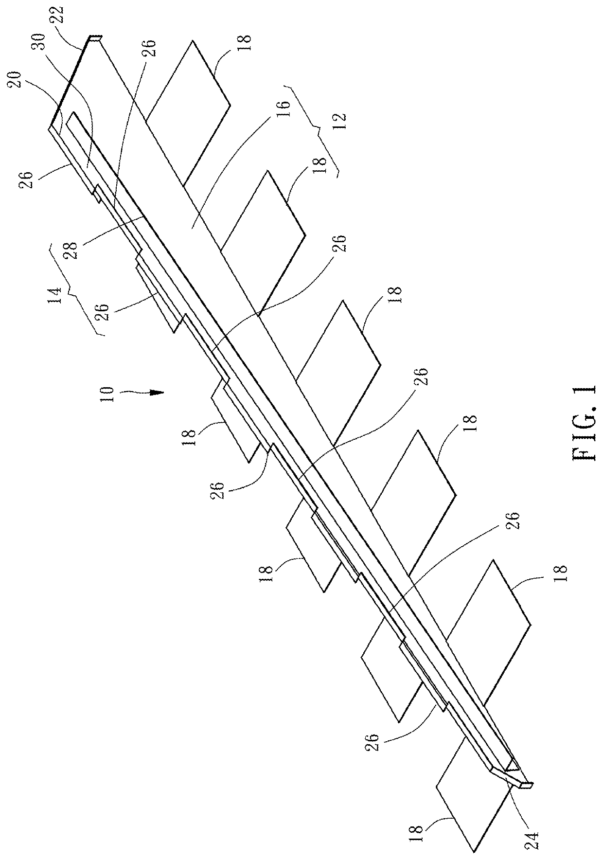
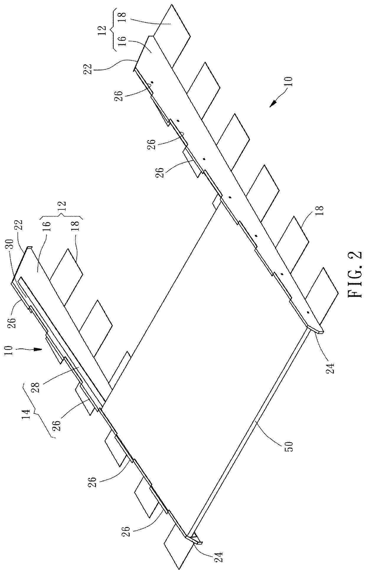
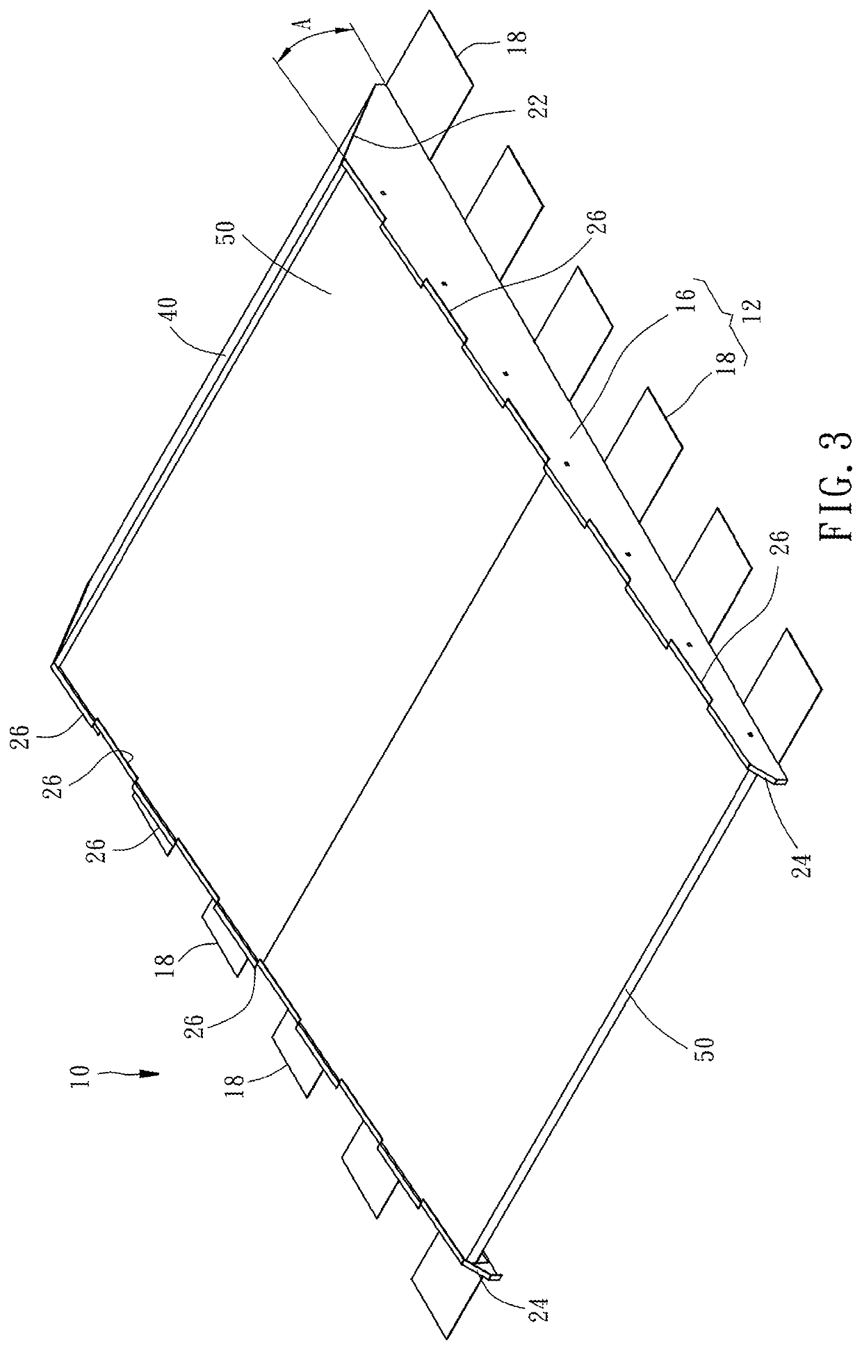
[0022]The technical contents and features of the present invention will now be described hereinafter with reference to the accompanying drawings. Those skilled in the art can understand that the description terms of the preferred embodiment belong to a higher-level description that does not limit the application field of solar power generation modules, for example, the term material or shape includes and is not limited to the material or shape specified in the description, the term location includes but is not limited to setting, approaching, connecting, or adjoining, and the number “a” of each component includes one and more than one component number. The directional adjectives such as “up”, “down”, “inside”, “outside”, “top”, and “bottom” mentioned in the contents of this specification are merely illustrative description terms based on the normal use direction, not as the purpose of limiting the scope of the claims.

[0023]As shown in FIG. 1 to FIG. 4, a modular support frame 10 for...


PUM


Abstract

A modular support frame for solar power assembly, includes a fixing part having a first end and a second end, and a coupling part having a guide groove extending between the first end and second end of the fixing part. An included angle is formed between the extending direction of the guide groove and the vertical direction so that a solar power assembly can be set between the first end and second end of the fixing part along the guide groove of the coupling part to achieve the invention object of convenient and fast assembly of a solar power assembly.

Description

BACKGROUND OF THE INVENTION1. Field of the Invention[0001]The present invention relates to solar power technology and more particularly, to a modular support frame for solar power assembly.2. Description of the Related Art[0002]Solar power modules are usually set on the roof of a building, or on an open and uncovered land, so that sunlight can be maximally radiated to the installed solar power modules. In this way, it can generate economically valuable power, and at the same time can achieve the purpose of protecting the environment in line with environmental protection and green energy.[0003]Generally, before setting up a solar power module, you must first use a number of steel combinations to form a scaffolding structure, and then tile all the solar power modules together, and then add a fixing method sufficiently to make the overall structure strong enough under various weather conditions without being damaged.[0004]However, the above-mentioned related components for the scaffold...

Claims


Application Information

Patent Timeline
Patent Type & Authority Applications(United States)
IPC IPC(8): H02S20/20
CPCH02S20/20F24S25/35F24S25/61F24S25/634H02S30/00H02S20/10H02S20/23Y02B10/10Y02E10/47Y02E10/50
Inventor YANG, CHING-LUNG
Owner JING XIN SOLAR LTD
Why Eureka
Try Eureka