
Non-contact model test observation method for dynamic development of plastic zone in load-bearing foundation

A model test, non-contact technology, applied in the direction of applying stable shear force to test material strength, measuring device, strength characteristics, etc., can solve the problems of undiscovered scientific research reports, undiscovered foundation plastic zone, horizontal static lateral pressure coefficient Changes and other issues, to achieve the effect of reducing post-data processing work, eliminating artificial disturbances, and improving efficiency

Inactive Publication Date: 2019-09-17
HUNAN INSTITUTE OF SCIENCE AND TECHNOLOGY
View PDF4 Cites 4 Cited by
  • Summary
  • Abstract
  • Description
  • Claims
  • Application Information

AI Technical Summary

Problems solved by technology

However, the existing theoretical derivations all assume that the soil is a homogeneous and isotropic ideal elastic-plastic material, and assume that the horizontal static lateral pressure coefficient of the soil is an empirical constant
However, in the actual situation, the foundation soil is a loose particle with anisotropic characteristics. Does the horizontal static lateral pressure coefficient change? Is the corresponding relationship between the shape of the plastic zone of the foundation, the plastic zone and the load it bears consistent with the theoretical analysis results under the hypothetical conditions? At present, no relevant scientific research reports have been found, and no literature descriptions have been found to study the characteristics of the plastic zone of the foundation by means of experiments.
[0004] Therefore, it is urgent to design a model test observation method that can be used to directly determine the development of the plastic zone of the subgrade under load, so as to fill the gap that can only be deduced theoretically but cannot be determined from the experimental point of view.

Method used


Image

  • Non-contact model test observation method for dynamic development of plastic zone in load-bearing foundation
  • Non-contact model test observation method for dynamic development of plastic zone in load-bearing foundation
  • Non-contact model test observation method for dynamic development of plastic zone in load-bearing foundation

Examples


Embodiment

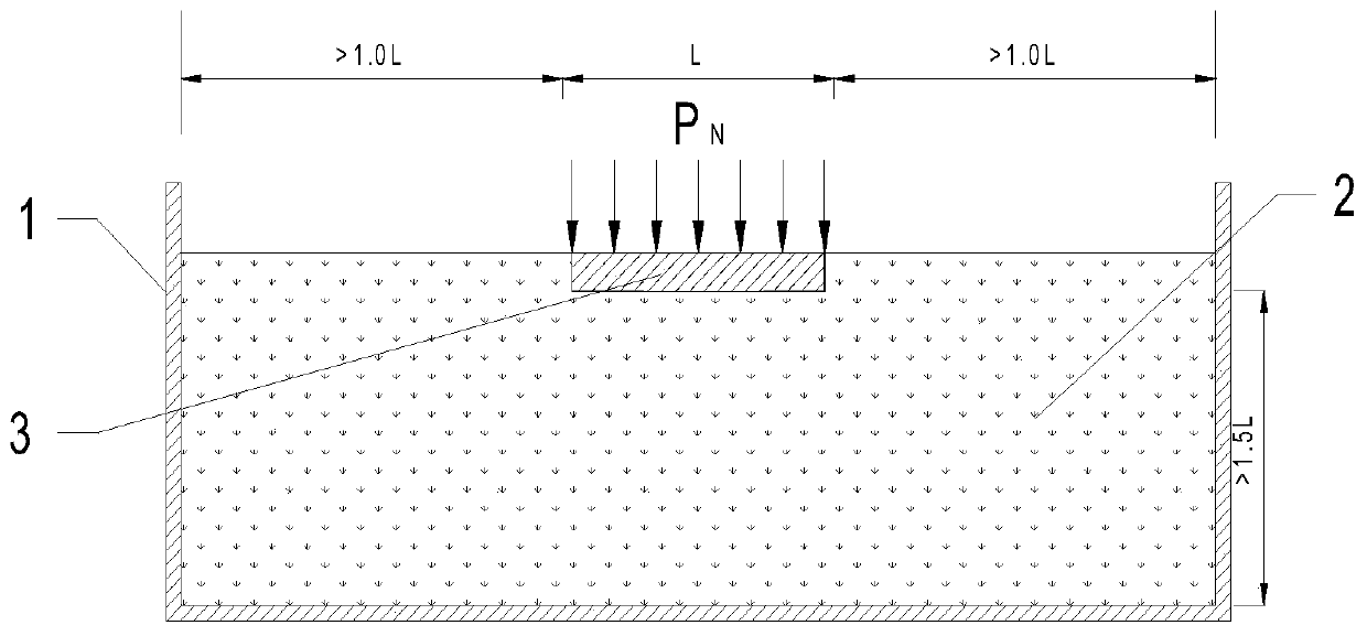
[0032] see figure 1 , a non-contact model test observation method for the dynamic development of the plastic zone of the loaded foundation, including the following steps:

[0033] S1. Make a model tank 1 with at least one side of a transparent plate, take the soil in the load-bearing area of ​​the foundation as the test soil 2, put it into the model tank 1, and compact it in layers to the same thickness as the soil in the load-bearing area of ​​the foundation Degree of compaction: the model tank 1 in this embodiment is made of 12 mm thick acrylic plate, before the test soil 2 is loaded into the model tank 1, the tree roots, stones and other sundries in the test soil 2 are removed in advance, and the test soil 2 is compacted The process adopts layered compaction, and the thickness of each layer after compaction is 5cm. In the present embodiment, at least one of the four sides of the model tank 1 is transparent, and toughened glass can be used so that the camera can take pictur...


PUM


Abstract

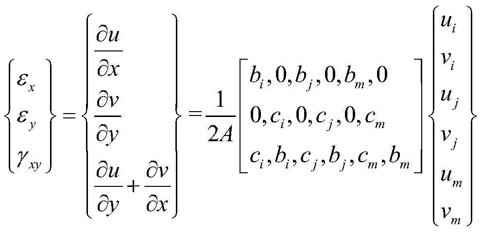
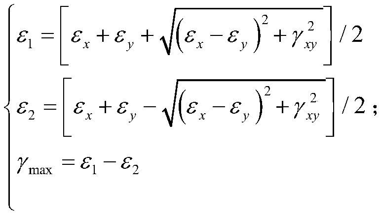
The invention relates to the technical field of geotechnical engineering test research, and discloses a non-contact model test observation method for dynamic development of a plastic zone in a load-bearing foundation. Displacement fields of the foundation under different load effects in a model test are obtained based on a particle image velocimetry (PIV) technology, then the displacement fields are converted into corresponding shearing variable fields, and finally a dynamic development law for the plastic zone in the load-bearing foundation is determined by analyzing a maximum shearing strain field under different load effects. The observation method for determining dynamic development of the plastic zone in the load-bearing foundation through the model test is proposed, the displacement fields are determined by using the particle image velocimetry technology according to a gradation loading model test for the plastic zone in the load-bearing foundation, and then the dynamic development low for the plastic zone in the load-bearing foundation is determined through secondary analysis; and a non-contact model test is adopted during testing, artifical disturbance of a foundation soil body in the test process is eliminated, later operation of data processing in a conventional method is reduced, and the efficiency is improved obviously.

Description

technical field [0001] The invention relates to the technical field of geotechnical engineering test research, in particular to a non-contact model test observation method for the dynamic development of the plastic zone of the loaded foundation. Background technique [0002] Particle image velocimetry (PIV) is a transient, multi-point, non-contact hydrodynamic velocimetry method developed in the late 1970s. White improved this technology for non-contact deformation measurement of soil in rock and soil tests; this technology uses a high-definition digital camera to continuously take a series of photos in real time, and digitizes all the photos. Through continuous analysis of two successive frames of digital images, In this way, the quantitative displacement field inside the soil can be obtained. [0003] At present, the analysis of the plastic zone of the foundation is determined on the basis of theoretical derivation, that is, the boundary equation of the plastic zone of th...

Claims


Application Information

Patent Timeline
Patent Type & Authority Applications(China)
IPC IPC(8): G01N3/24
CPCG01N3/24G01N2203/0025G01N2203/0075G01N2203/0258G01N2203/0641G01N2203/0676G01N2203/0682
Inventor 刘正夫刘晓红曾永庆陆仲阳张政张建伟彭锟姜豪徐川刘王苗
Owner HUNAN INSTITUTE OF SCIENCE AND TECHNOLOGY
Learn More