Rotary knob with rotating outer ring

A knob and outer ring technology, applied in the direction of instruments, control components, mechanical control devices, etc., can solve problems such as affecting aesthetics and affecting people's visual habits.

Pending Publication Date: 2019-09-20
ZHUHAI DOUBLE HAPPINESS ELECTRIC APPLIANCE
View PDF0 Cites 1 Cited by
  • Summary
  • Abstract
  • Description
  • Claims
  • Application Information

AI Technical Summary

Problems solved by technology

The knob of the existing design is usually a single knob. When the knob is turned, the words or lights on the knob also turn together with the knob, which not only affects the appearance but also affects people's visual habits.

Method used


Image

  • Rotary knob with rotating outer ring
  • Rotary knob with rotating outer ring
  • Rotary knob with rotating outer ring

Examples


Embodiment Construction

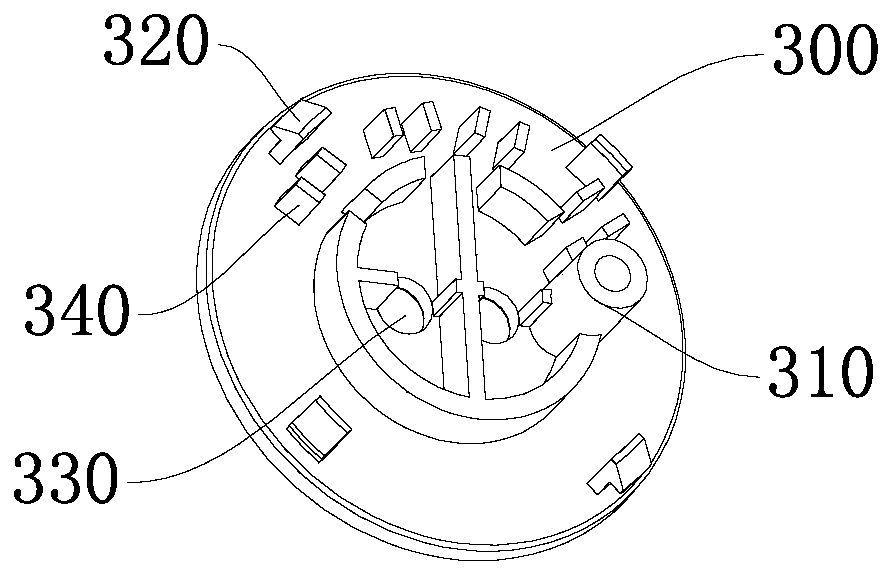
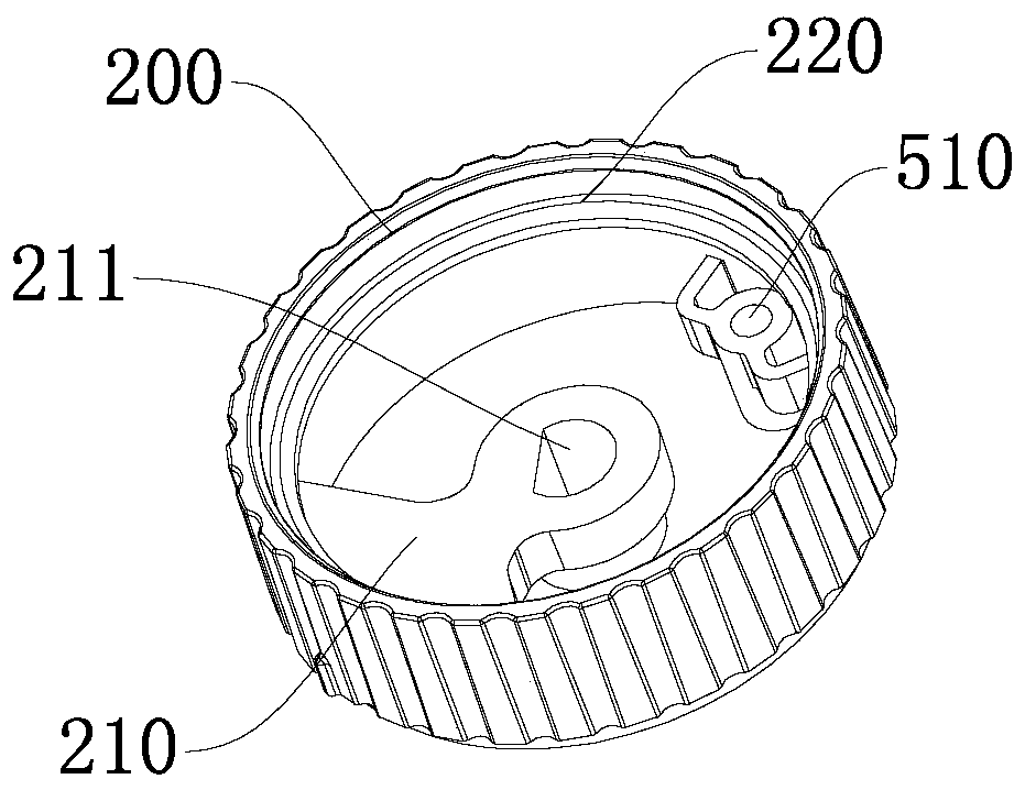
[0023] Such as figure 1 The shown rotary knob of the outer ring consists of: including a knob base 100, a knob cover 200, a knob cover 300 and a control element 400, the knob cover 200 is rotatably sleeved on the knob base 100, and the knob cover 300 is rotatably buckled on the knob The sleeve 200 is fixedly connected with the knob base 100, the control element 400 is fixedly connected with the knob base 100, the knob sleeve 200 is connected with the control element 400 to drive the control element 400 to adjust the gear, and the knob cover 300 is provided with a marking device.

[0024] The knob cover 300 is fixedly connected with the knob seat 100 to form a rigid body. The knob cover 200 can freely rotate between the knob cover 300 and the knob seat 100, and drives the related control element 400 to move to the corresponding control function position. During the rotating process, the knob cover 300 will not rotate because it is fixedly connected with the knob base 100, so th...


PUM


Abstract

The invention discloses a rotary knob with a rotating outer ring. The rotary knob comprises a knob base, a knob sleeve, a knob cover and a control element. The knob sleeve sleeves the knob base in a rotating manner. The knob cover is buckled into the knob sleeve and is fixedly connected with the knob base. The control component is fixedly connected to the knob base. The knob sleeve is connected with the control element in a rotating manner to drive the control element to adjust the gear position. An identification device is arranged at the knob cover. The knob cover and the knob base are fixedly connected to form a rigid body. The knob sleeve can rotate freely between the knob cover and the knob base and the related control element is driven to move to a corresponding control function position. When the knob sleeve rotates, the knob cover does not rotate with the knob sleeve and thus the identification device arranged at the knob cover does not rotate, thereby conforming to the user's visual habits well and ensuring the aesthetic appearance of the product. The rotary knob is applied to electrical equipment.

Description

technical field [0001] The invention relates to the technical field of electrical equipment, in particular to a knob whose outer ring rotates. Background technique [0002] A knob is a manual part that is rotated by hand. It is often used to drive the control element to rotate to turn on or off the control circuit, so as to achieve the purpose of controlling the operating state of electrical equipment. Knobs used in electrical appliances and related products are used to drive components such as timers or potentiometers to rotate to achieve timing, change resistance or achieve corresponding control functions. [0003] The knob is generally provided with an indicator light or text to explain the function corresponding to the corresponding position of the knob. The knob of existing design is usually a single knob, and when the knob rotates, the words or lights on the knob also rotate together with the knob, which not only affects the appearance but also affects people's visual...

Claims


Application Information

Patent Timeline
Patent Type & Authority Applications(China)
IPC IPC(8): G05G1/10
CPCG05G1/10
Inventor 龚盛鹏高铭姜天恩
Owner ZHUHAI DOUBLE HAPPINESS ELECTRIC APPLIANCE
Why Eureka
Try Eureka