
Obstacle-crossingclimbing rod device and climbing rod method thereof

A technology of pole climbing and telescopic device, which is applied in the field of climbing poles and can solve problems such as inability to avoid

Active Publication Date: 2019-09-24
ELECTRIC POWER RES INST OF STATE GRID ANHUI ELECTRIC POWER +2
View PDF10 Cites 5 Cited by
  • Summary
  • Abstract
  • Description
  • Claims
  • Application Information

AI Technical Summary

Problems solved by technology

[0006] One of the technical problems solved by the present invention is that existing pole climbing devices cannot avoid obstacles when they encounter obstacles in the process of climbing poles

Method used


Image

  • Obstacle-crossingclimbing rod device and climbing rod method thereof
  • Obstacle-crossingclimbing rod device and climbing rod method thereof
  • Obstacle-crossingclimbing rod device and climbing rod method thereof

Examples


Embodiment 1

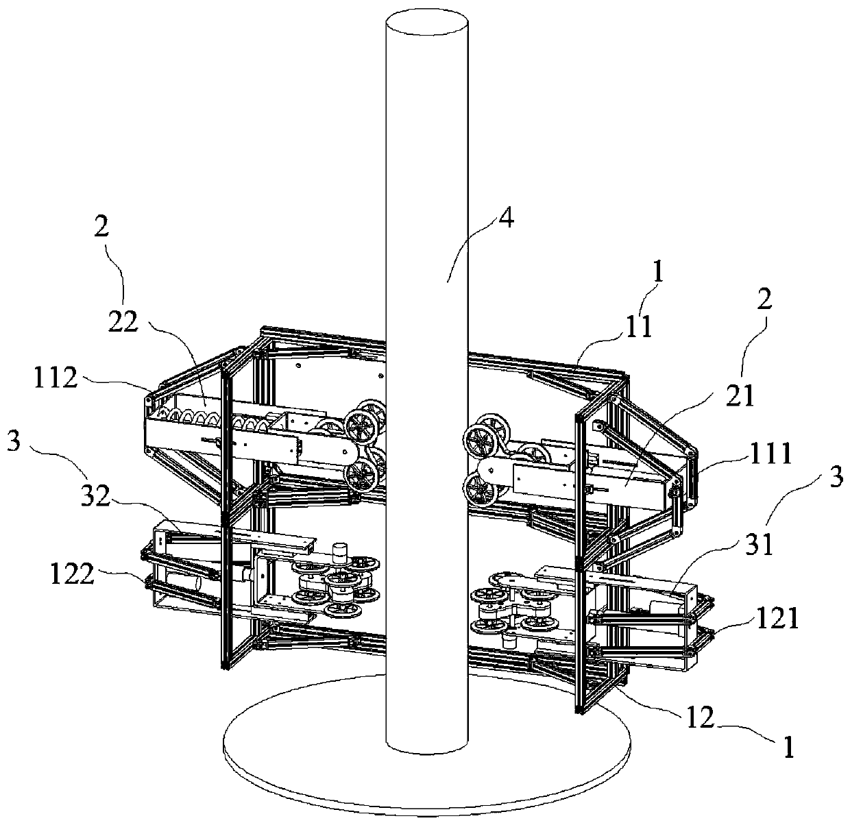
[0098] Such as figure 1 As shown, an obstacle climbing pole device includes a frame 1, an obstacle climbing mechanism 2, and a pole revolving mechanism 3. Both the obstacle climbing mechanism 2 and the pole revolving mechanism 3 are fixed on the frame 1, and the obstacle climbing mechanism The mechanism rises or falls along the axis of the target rod 4, and the rod-circling mechanism moves around the target rod 4 in the circumferential direction.

[0099] Such as figure 1 As shown, the frame 1 includes a first frame 11 and a second frame 12, the first frame 11 and the second frame 12 are all three-dimensional frame structures, and the lower end of the first frame 11 is connected to the second frame in this embodiment. The upper end of frame 12 is fixedly connected; In order to make the obstacle climbing device can pass target rod 4 along the radial direction of target rod 4, the side of first frame 11 is provided with first opening, and the side of second frame 12 is provided...

Embodiment 2

[0154] The difference between this embodiment and embodiment 1 is: as Figure 10 As shown, a pressure sensor 217 is also included, the pressure sensor 217 is installed between the electric push rod one 216 and the triangular roller support plate one 213, the pressure sensor 217 is connected with the control board (not shown), and the control board and the electric push rod -216 connection, the pressure sensor 217 and the control board in the present embodiment are prior art.

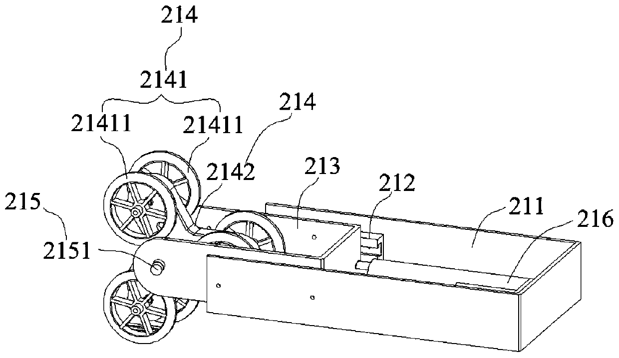
[0155] The working principle of this embodiment: when both the roller group 1 2141 and the roller group 2241 encounter obstacles during the climbing process, the highest height of the obstacle encountered by the roller group 2241 extending outward along the radial direction of the target rod 4 is recorded as h2, the maximum height of the obstacle encountered by the roller group 1 2141 extending outward along the radial direction of the target rod 4 is denoted as h1, when h1 is greater than or equal to h2...


PUM


Abstract

The invention discloses an obstacle-crossingclimbing rod device, and relates to the technical field of climbing rods. The obstacle-crossingclimbing rod device is provided to solve the problem that an existing climbing rod device cannot avoid obstacles encountered in the climbing process.The obstacle-crossingclimbing rod device comprises a rack, an obstacle-crossing climbing mechanism and a rotating-around-rodmechanism. The obstacle-crossing climbing mechanism and the rotating-around-rod mechanismare located on the rack, an opening is formed in one side of the rack, the obstacle-crossing climbing mechanism and the rotating-around-rod mechanism are located in the opening; the obstacle-crossing climbing mechanism comprises a first obstacle-crossing climbing mechanism and a second obstacle-crossing climbing mechanism; the rotating-around-rod mechanism comprises a first rotating-around-rod mechanism and a second rotating-around-rod mechanism. The invention also provides a climbing rod method of the obstacle-crossingclimbing rod device. The obstacle-crossingclimbing rod device and the climbing rod method thereof has the beneficial effects that when encountering obstacles in the process of climbing, the obstacle-crossing climbing mechanism can avoid the obstacles on the target bar through the rotating-around-rod mechanism,not be limited by the size of obstacles andcan climb and rotate at the same time.

Description

technical field [0001] The invention relates to the technical field of pole climbing, in particular to an obstacle climbing pole climbing device and a pole climbing method thereof. Background technique [0002] In various operations, it is often necessary to perform pole climbing operations. Traditional pole climbing operations are carried out manually, that is, operators rely on various auxiliary devices to climb poles to achieve various operations, but the realization of this method has great limitations. First, the pole climbing operation is still an extremely labor-intensive job, which requires high physical requirements for the pole climbing personnel; second, the pole climbing operation is very dangerous, and there is a risk of falling if you are not careful. Difficulty, thus increasing the risk factor. [0003] With the development of the machinery industry, the pole climbing device will gradually replace humans to complete some high-strength, high-repetition, high-r...

Claims


Application Information

Patent Timeline
IPC IPC(8): B62D57/024B60K1/02
CPCB62D57/024B60K1/02E02B17/0034
Inventor 冯玉吴少雷凌松吴凯赵成陆巍史亮程凯王伟
Owner ELECTRIC POWER RES INST OF STATE GRID ANHUI ELECTRIC POWER
Learn More