
Key structure

A button and keycap technology, which is applied in the field of magnetic button structure, can solve the problems of affecting elasticity, the button cannot be sunken for storage, and the button occupies space, so as to achieve the effect of easy storage

Inactive Publication Date: 2019-09-24
DARFON ELECTRONICS (SUZHOU) CO LTD +1
View PDF0 Cites 3 Cited by
  • Summary
  • Abstract
  • Description
  • Claims
  • Application Information

AI Technical Summary

Problems solved by technology

For notebook computers, when the user does not need to use the notebook computer, the user will close the screen. Since the traditional buttons cannot be sunken for storage, the screen may collide with the buttons and be damaged.
In addition, the buttons that cannot be sunken and stored take up more space, which limits the thinning of notebook computers
In addition, if the button structure adopts the design of providing the restoring force of the keycap through an elastic member (such as a silicone dome), when the keycap is forced to sink for easy storage, the elastic member will be in a compressed state for a long time in principle. May cause permanent deformation and affect elasticity, which is not conducive to the service life of elastic components

Method used


Image

  • Key structure
  • Key structure
  • Key structure

Examples


Embodiment Construction

[0040] The following descriptions of the various embodiments refer to the accompanying drawings to illustrate specific embodiments in which the invention may be practiced. The directional terms mentioned in the present invention, such as "up", "down", "front", "rear", "left", "right", "side", etc., only refer to the directions of the attached drawings. Therefore, the directional terms used are for describing and understanding the present invention, not for limiting the present invention.

[0041] In the following embodiments, the same parts are denoted by the same reference numerals in different drawings.

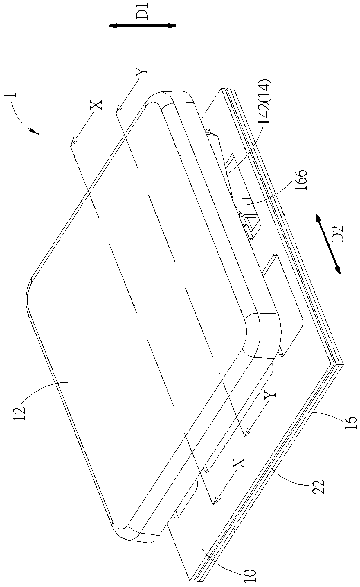
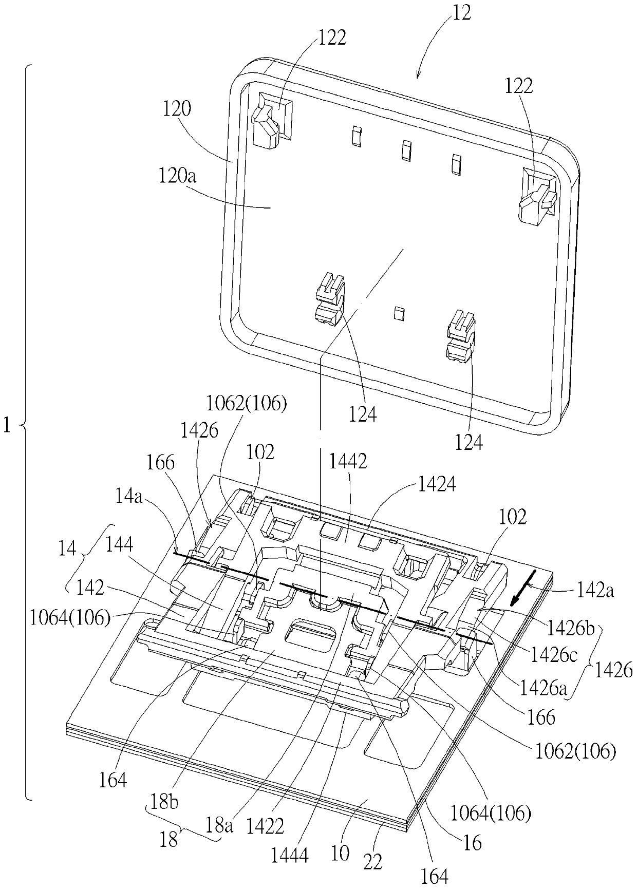
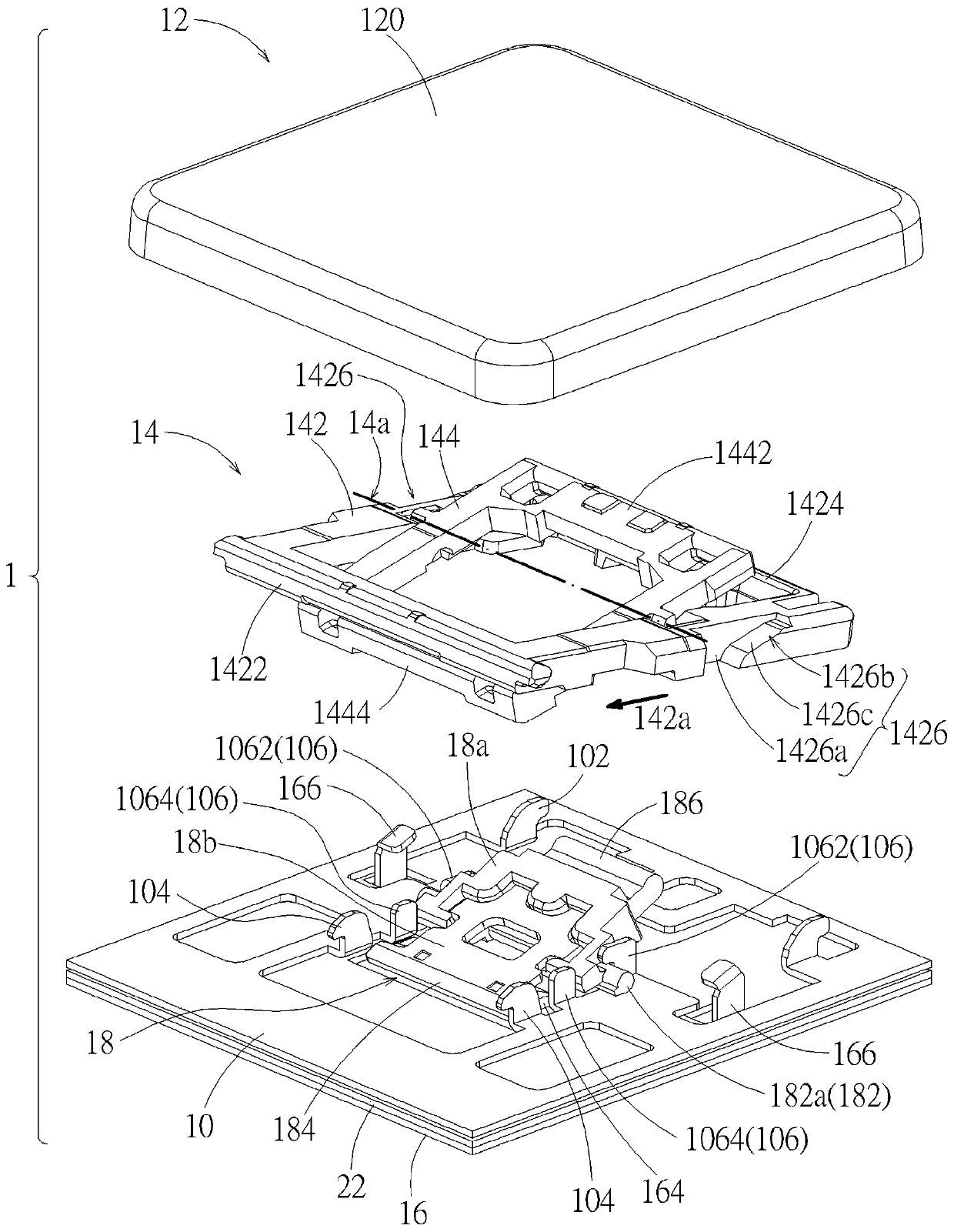
[0042] see Figure 1 to Figure 10 . The key structure 1 according to an embodiment includes a bottom plate 10 , a key cap 12 , a scissor foot support frame 14 , a movable member 16 , a linkage bracket 18 , a magnetic attraction member 20 and a switch circuit board 22 . The keycap 12 is disposed on the bottom plate 10 . The scissor foot support frame 14 is disposed betwe...


PUM


Abstract

The invention discloses a key structure, which includes a base plate, a key cap, a scissors foot support frame, a linkage bracket, a movable member and a magnetic attraction member, wherein the scissors foot support frame is connected with the base plate and the key cap; the movable member is slidably arranged relative to the base plate; the linkage bracket is rotatably arranged on the base plate and provided with a magnetic attraction part and a driving part; and the magnetic attraction member is arranged on the movable member and can generate magnetic attraction with the magnetic attraction part. When the movable member is located at the first position, the magnetic attraction member is located below the magnetic attraction part, and the magnetic attraction drives the key cap to move away from the base plate via the linkage bracket. In addition, when the movable member moves from the first position to the second position, the magnetic attraction member is away from the magnetic attraction part, the magnetic attraction is reduced to enable the key cap to move towards the base plate. According to the key structure of the invention, the keycap can sink for storage even if the key cap is not subjected to external pressure. Furthermore, the restoring force, namely, the magnetic attraction, of the key cap is not generated by an elastic structure, so that there is no such a problem that an elastic component in the prior art may be permanently deformed and affect the elasticity.

Description

technical field [0001] The invention relates to a magnetic suction key structure, in particular to a magnetic suction key structure with a keycap that can be sunk and received. Background technique [0002] The traditional notebook computer keyboard does not have a sunken storage design, so no matter whether the computer screen is opened or closed, the keycaps remain at the same height (unpressed position), so the traditional keyboard has a fixed height. For a notebook computer, when the user does not need to use the notebook computer, the user closes the screen. Since the traditional keys cannot be sunk and stored, the screen may collide with the keys and be damaged. In addition, the keys that cannot be sunk and stored take up more space, which limits the thinning of the notebook computer. In addition, if the key structure adopts the design of providing the restoring force of the keycap through an elastic member (such as a silicone dome), when the keycap is forced to sink ...

Claims


Application Information

Patent Timeline
Patent Type & Authority Applications(China)
IPC IPC(8): H01H13/12H01H3/12
CPCH01H13/12H01H3/125H01H2227/036H01H2221/04H01H2231/002
Inventor 谢铭元叶亮达
Owner DARFON ELECTRONICS (SUZHOU) CO LTD
Learn More