
Preparation method of curved surface backlight module, curved surface backlight module and display device

A backlight module and curved surface technology, applied in optics, nonlinear optics, instruments, etc., can solve the problems of increased risk of light source short circuit, dead light of backlight module, easy to break, etc., to prevent dead light or short circuit of light source , Solve the effect of dead lights and prevent breakage

Active Publication Date: 2021-04-09
XIAMEN TIANMA MICRO ELECTRONICS
View PDF9 Cites 0 Cited by
  • Summary
  • Abstract
  • Description
  • Claims
  • Application Information

AI Technical Summary

Problems solved by technology

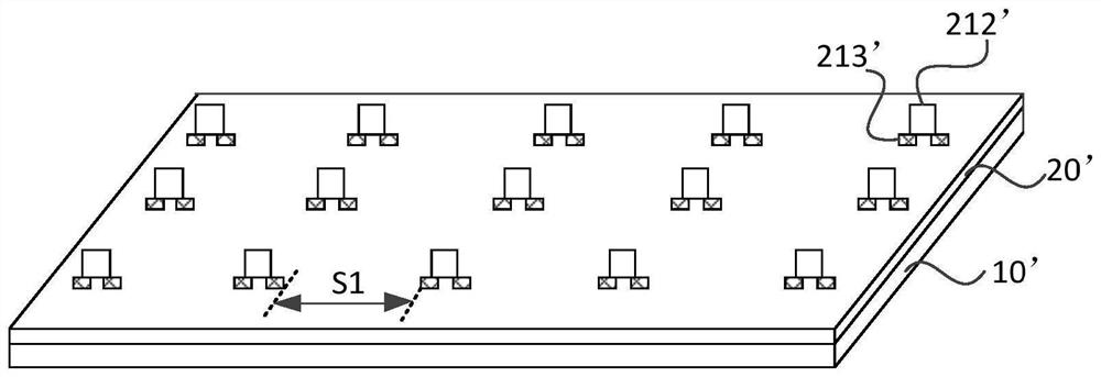
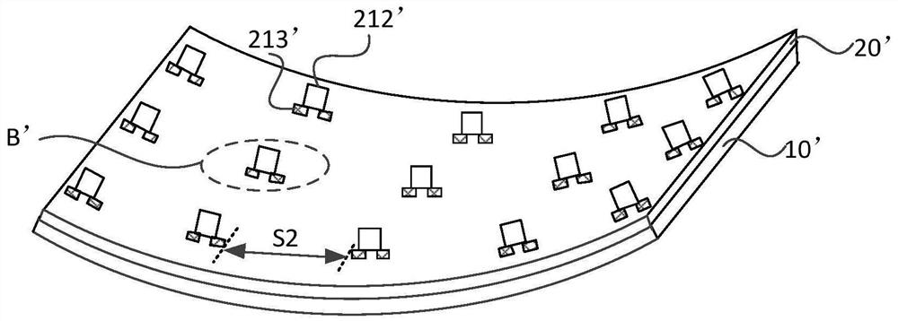
[0004] However, when the light board is in a naturally flattened state, the horizontal distance between the pads of two adjacent light sources can be recorded as S1; when the light board is bent with the back plate, the horizontal distance between the pads of two adjacent light sources It can be recorded as S2. Obviously, due to the bending of the light board, S2 will be smaller than S1, that is, the distance between the solder pads of two adjacent light sources will decrease after the light board is bent with the back plate, resulting in the distance between the adjacent two light sources. increased risk of short circuits between
In addition, when the lamp board is bent with the back board, the welding pads of the light source are prone to breakage or false welding due to the extrusion of the lamp board, which will cause the backlight module to die.

Method used


Image

  • Preparation method of curved surface backlight module, curved surface backlight module and display device
  • Preparation method of curved surface backlight module, curved surface backlight module and display device
  • Preparation method of curved surface backlight module, curved surface backlight module and display device

Examples


Embodiment Construction

[0048] The present invention will be further described in detail below in conjunction with the accompanying drawings and embodiments. It should be understood that the specific embodiments described here are only used to explain the present invention, but not to limit the present invention. In addition, it should be noted that, for the convenience of description, only some structures related to the present invention are shown in the drawings but not all structures.

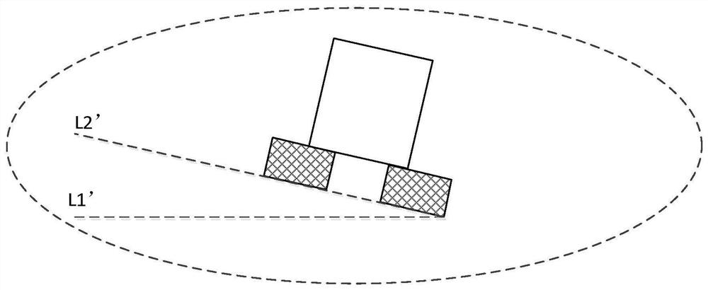
[0049] figure 1 It is a structural schematic diagram of an initial backplane and an initial lamp panel provided by the prior art. figure 2 It is a structural schematic diagram of a curved surface backlight module provided by the prior art. image 3 yes figure 2 The enlarged schematic diagram at B' in the middle. see figure 1 and figure 2, the method for preparing a curved surface backlight module in the prior art includes: firstly, providing an initial lamp board 20', the initial lamp board 20' includes op...


PUM


Abstract

The embodiment of the invention discloses a preparation method of a curved surface backlight module, a curved surface backlight module and a display device. Including: providing an initial back plate, the initial back plate includes opposite first and second faces; the first face includes a plurality of first flat areas and a plurality of first convex curved areas; the first convex curved areas are located on opposite sides Adjacent to the first flat area; the second surface includes a plurality of second flat areas and a plurality of first concave bending areas; an initial lamp board is provided, and a plurality of light sources are welded on the front side of the initial lamp board through pads; the initial The back of the light panel is laid on the first side of the original backplane; the back of the initial light panel faces away from the front; the light source is located in the first flat area; the initial backplane and the initial light panel are bent to form a curved backlight module; the curved backlight module The direction of the bending axis is parallel to the bending axis of the first convex bending zone and the bending axis of the first concave bending zone. The technical solution provided by the embodiment of the present invention can prevent the light source of the curved surface backlight module from dead light or short circuit.

Description

technical field [0001] The embodiments of the present invention relate to the technical field of curved surface display, and in particular to a method for preparing a curved surface backlight module, a curved surface backlight module, and a display device. Background technique [0002] A curved display device refers to a display device with a certain curvature of the screen, which has the advantages of better contrast and wider viewing angles, and has broad market prospects in the fields of automobiles, wearables, televisions, and mobile communications. [0003] For the curved liquid crystal display device, not only the liquid crystal display panel has a certain curvature, but also the backlight module and the liquid crystal display panel will be adaptively curved after being assembled. In the prior art, a backlight module usually includes a backplane, a lamp board, and a light source. Generally, the light source is first welded to the lamp board through a pad, and then the ...

Claims


Application Information

Patent Timeline
Patent Type & Authority Patents(China)
IPC IPC(8): G02F1/13357
CPCG02F1/133608G02F1/133603
Inventor 洪金龙
Owner XIAMEN TIANMA MICRO ELECTRONICS
Learn More