Connection method for split wheel-installed brake disk

A connection method and brake disc technology, applied in the direction of the brake disc, brake type, brake components, etc., can solve the problems of inconvenient operation, long cycle, increased labor and material cost, etc.

Active Publication Date: 2019-10-08
BEIJING JIAOTONG UNIV
View PDF8 Cites 4 Cited by
  • Summary
  • Abstract
  • Description
  • Claims
  • Application Information

AI Technical Summary

Problems solved by technology

For the structure of the existing wheel-mounted brake disc, when replacing the brake disc, the wheel needs to be removed first, and then the replacement can be performed. The operation is inconvenient and the cycle is long, especially during the process of removing the wheel, it will cause damage to the hub hole and the axle box bearing, which will increase maintenance. Manpower and material costs in the maintenance process

Method used


Image

  • Connection method for split wheel-installed brake disk
  • Connection method for split wheel-installed brake disk
  • Connection method for split wheel-installed brake disk

Examples


Embodiment 1

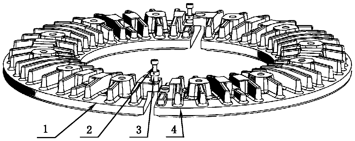
[0022] A method for connecting a split wheel-mounted brake disc, comprising a disc body A 1 and a disc body B 4, a positioning sleeve and a hexagon socket head screw 2, the disc body A 1 and the disc body B 4 have exactly the same structure, and the disc body A 1 and the back side of the disk body B 4 are slat-shaped cooling ribs, such as figure 1 shown.

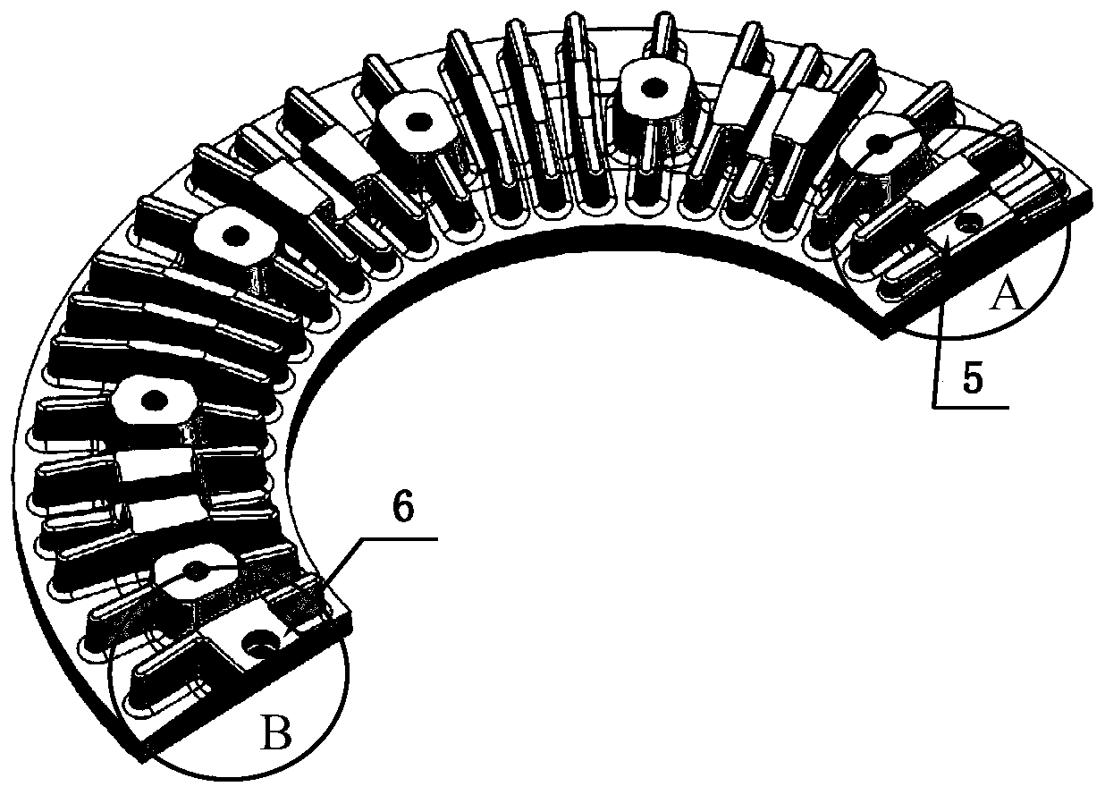
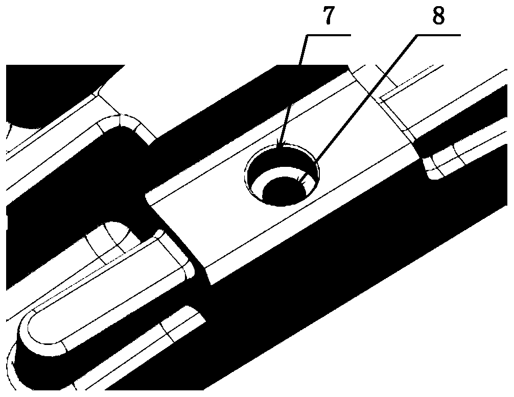
[0023] The two ends of the disc body A 1 and the disc body B 4 are respectively arranged with grooves 5 and flanges 6, the grooves 5 are provided with positioning holes A7 and threaded holes 8, and the flanges are provided with counterbores 10 and positioning holes B9, like figure 2 , image 3 , Figure 4 , Figure 5 shown.

[0024] The positioning sleeve 3 passes through the flange 6 and the groove 5 accordingly to realize the radial and circumferential positioning of the disk body A1 and the disk body B4, such as figure 1 As shown, the hexagon socket head cap screw 2 is tightened through the positioning sleeve 3 and...


PUM


Abstract

The invention provides a connection method for a split wheel-installed brake disk. A disk body A (1) and a disk body B (4) used by the connection method have identical structures. Grooves (5) and flanges (6) are respectively arranged at two ends of the disk body A and disk body B. Locating holes A (7) and threaded holes (8) are formed in the grooves. Counter bores (10) and locating holes B (9) areformed in the flanges (6). Locating sleeves (3) penetrate through the flanges (6) and the grooves (5) in sequence, and radial direction and circumferential direction location of disk body A (1) and disk body B (4) is achieved. Withdrawal holes (13) are formed in the locating sleeves. Inner hexagon screws (2) penetrate through the locating sleeves (3) and are screwed tightly with the threaded holes (8), axial direction location of disk body A (1) and disk body B (4) is achieved, and thus full-constrained reliable connection of displacement of disk body A (1) and disk body B (4) is achieved.

Description

technical field [0001] The invention relates to a method for connecting wheel-mounted brake discs for rail vehicles, which is suitable for various types of rail trains using wheel-mounted brake discs. [0002] technical background [0003] For rail transit trains with a speed of more than 160km / h, disc brakes are generally used, including wheel-mounted brake discs and axle-mounted brake discs. The wheel-mounted brake discs are located on both sides of the wheel, and are closely attached to the wheel spokes through positioning posts and bolt fasteners. [0004] The brake disc is subjected to the combined action of various loads during the braking process, as well as the wear from the brake pads. The failure of the brake disc is usually manifested as wear-to-limit failure and friction surface fatigue crack length over-limit failure. During the operation and maintenance of trains, it is often necessary to replace the brake disc due to the failure of the brake disc. At present,...

Claims


Application Information

Patent Timeline
Patent Type & Authority Applications(China)
IPC IPC(8): F16D65/12
CPCF16D65/12F16D2065/134
Inventor 杨智勇韩建民李志强李卫京刘小龙
Owner BEIJING JIAOTONG UNIV
Why Eureka
Try Eureka